
Interposer one-step load and self-lock socket

a one-step load and self-locking technology, applied in the direction of fixed connections, coupling device connections, electrical apparatus construction details, etc., can solve the problems of insufficient electrical contact with regard to one or more of the bumps, increase in bumps as well as difficulty and cost to change the component, and avoid the complexity and cost. , the effect of eliminating the possibility of cold welding

Inactive Publication Date: 2005-04-26
HEWLETT-PACKARD ENTERPRISE DEV LP +1
View PDF18 Cites 1 Cited by
  • Summary
  • Abstract
  • Description
  • Claims
  • Application Information

AI Technical Summary

Benefits of technology

[0013]The configuration of the preferred embodiment permits the socket to simply be “clicked” into place and avoids the complexity and cost associated with tensioning screws by a prescribed amount of torque. Further, the potential for cold welding is also eliminated as the preferred embodiment avoids the use of screws being turned under large amounts of force. These and other aspects of the present invention will become apparent upon studying the following detailed description, figures and claims.

Problems solved by technology

Although generally satisfactory, soldering a component directly to the board makes it difficult and costly to change that component should it be desired or necessary to replace one component with another.
That is, for various reasons, over time substantially less than 100 grams of force per bump may eventually result in an insufficient electrical contact with regard to one or more of the bumps.
As the size of the electrical components being retained by such socket increases, the number of bumps increases as well.
As the total force increases with the use of stiffer springs, the friction increases and, in a relatively small percentage of cases, actually can cause the screw 16 to become welded to the post 20 preventing the screw from being turned further, preventing sufficient force to be applied to the component and perhaps causing the screw to break.
Also, metallic particles can be created when the screws are tightened which can short some of the contacts and cause damage to the chip.
Obviously, these sorts of problems are undesirable.
These problems will no doubt become even more severe as chip size grows.

Method used


Image

  • Interposer one-step load and self-lock socket
  • Interposer one-step load and self-lock socket
  • Interposer one-step load and self-lock socket

Examples


Embodiment Construction

[0024]The preferred embodiment of the invention is described below in the context of a processor chip and heat sink combination mounted on a circuit board with an interposer socket. It should be noted, however, that the chip need not be a processor nor is the heat sink required. Broadly, the invention is useful to reduce vibration for any type of component mounted to a circuit board.

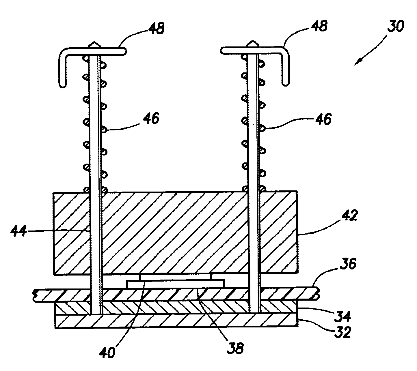
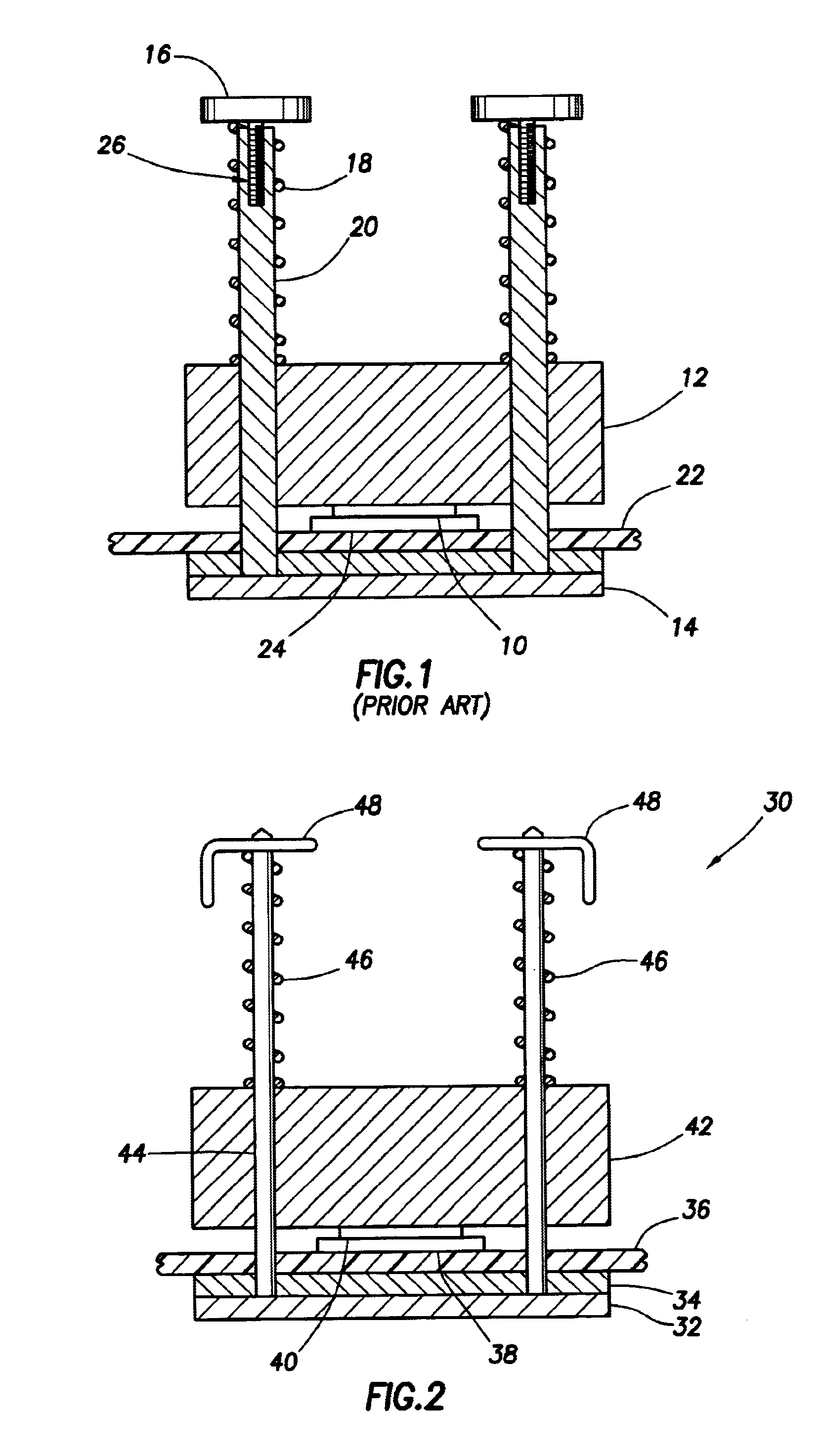
[0025]Referring now to FIG. 2, a restraint system 30 is shown to attach a processor 40 and associated heat sink 42 to a circuit board 36. In accordance with the preferred embodiment of the invention, the restraint system 30 includes a backing plate 32 from which a plurality of posts 44 protrude vertically therefrom, an insulator 34 to prevent the backing plate 32 from electrically interfering with the circuit board, an interposer socket 38, springs 46, and clips 48. As shown, the posts 44 protrude upward through corresponding holes in the insulator 34, circuit board 36 and heat sink 42. Springs 46 have a...


PUM


Abstract

A self-locking interposer restraint mechanism is disclosed. Rather than using screws to compress springs, clips are pushed down over the posts to compress the springs. Once the clips are pushed down to a level at which the springs are sufficiently compressed, the clips engage stops fabricated into the posts thereby locking the restraint mechanism.

Description

CROSS-REFERENCE TO RELATED APPLICATIONS[0001]Not applicable.STATEMENT REGARDING FEDERALLY SPONSORED RESEARCH OR DEVELOPMENT[0002]Not applicable.BACKGROUND OF THE INVENTION[0003]1. Field of the Invention[0004]The present invention generally relates to electrical sockets used to mount electrical components on a circuit board. More particularly, the present invention relates to interposer sockets and more particularly still to an interposer socket that includes a self-locking feature.[0005]2. Background of the Invention[0006]For many decades, circuit boards, such as those used in computers, have been manufactured by attaching electrical components to the board. In some cases, the components are soldered directly to the board. Although generally satisfactory, soldering a component directly to the board makes it difficult and costly to change that component should it be desired or necessary to replace one component with another. A microprocessor, for example, may have hundreds of connect...

Claims


Application Information

Patent Timeline
Patent Type & Authority Patents(United States)
IPC IPC(8): H01R43/26H01R12/55
CPCH01L23/4093H01R12/7047H01R12/52H01R13/6277H01L2924/0002H01L2924/00
Inventor IANNUZZELLI, RAYMOND J.CALLAHAN, DANIEL L.TOUSIGNANT, PHILIP R.
Owner HEWLETT-PACKARD ENTERPRISE DEV LP
Learn More