High deflection hydrofoils and swim fins

a high-deflection, hydrofoil technology, applied in swimming aids, swimming fins, swimming, etc., can solve the problems of losing the scoop advantage, the depth of the collapsed scoop is very small or often negligible, and the blades using flexible blades that flex to form a scoop shape during use are vulnerable to longitudinal compression forces

Inactive Publication Date: 2005-04-26
MCCARTHY PETER T
View PDF153 Cites 33 Cited by
  • Summary
  • Abstract
  • Description
  • Claims
  • Application Information

AI Technical Summary

Benefits of technology

[0166]Accordingly, the reader will see that the methods of the present invention can be used to permit scooped swim fin blades to flex around a transverse axis to a significantly reduced angle of attack while reducing or preventing the scooped portion of the blade from collapsing or buckling under the longitudinal compression forces exerted on the scooped portion during a large scale blade deflection. Although it is preferred that the blade or hydrofoil is at a relatively high deflection during use, any of the methods or structures disclosed can be used with hydrofoils or blades at a relatively low deflection during use. Lower deflections and, or higher angles of attacks can be used as well.

Problems solved by technology

Prior art swim fin blades using flexible blades that flex to form a scoop shape during use are vulnerable to longitudinal compression forces if the entire blade system bends around a transverse axis to a reduced angle of attack.
Because prior art blade designs do not recognize this problem or provide any suitable solutions, the blade's resistance to contraction prevents the blade from forming the scoop shape during use and the scoop advantage is lost.
As a result, only a small portion of the blade's surface area near the tip of the fin is able to form a scoop and the back pressure within the blade also causes the depth of the collapsed scoop to be very small or often negligible.

Method used


Image

  • High deflection hydrofoils and swim fins
  • High deflection hydrofoils and swim fins
  • High deflection hydrofoils and swim fins

Examples


Embodiment Construction

. 1

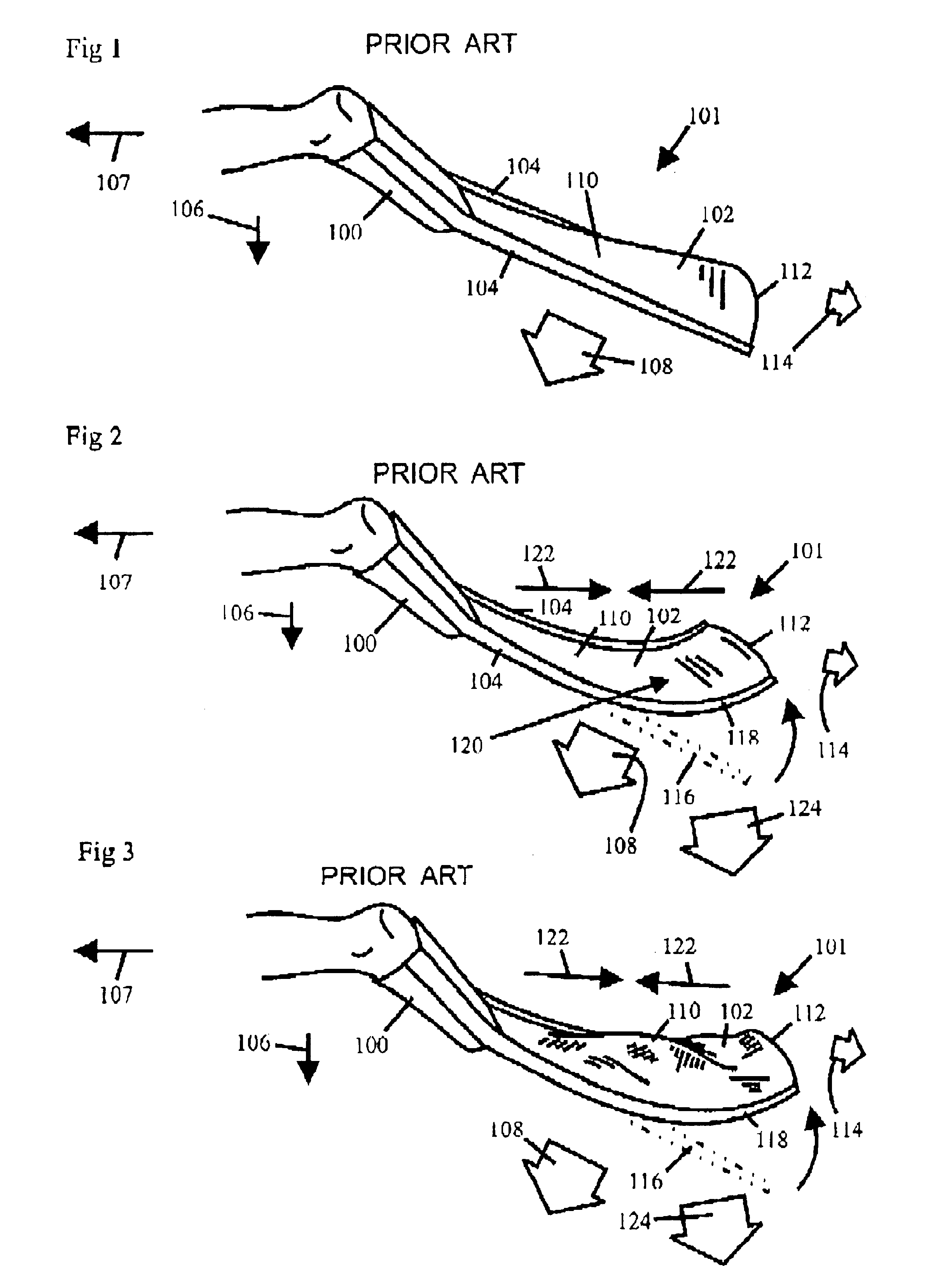
[0051]FIG. 1 shows a prior art swim fin that does not deflect around a transverse axis. The swim fin has a foot pocket 100 and a blade region 101. Blade region 101 has a blade 102, and two stiffening members 104. The swimmer is kicking the swim fin in a kick direction 106 with the intention of moving in a travel direction 107. In this example, stiffening members 104 are very rigid and do not flex significantly around a transverse axis during use. Blade 102 is sufficiently flexible to bow between stiffening members 104 to form a scoop shape during use. Most of the water along blade 102 is moved in a flow direction 108, which is shown by a large arrow. Flow direction 108 is perpendicular to the lengthwise alignment of blade 102 and stiffening members 104. Flow direction 108 is seen to be aimed in a downward direction that is angled in the wrong direction for propelling in travel direction 107. Blade 102 is seen to have a lee surface 110 and a forward edge 112 that is bowed to form ...


PUM


Abstract

Designs and methods are disclosed for permitting permit scooped shaped swim fin blades (184) to flex around a transverse axis to a significantly reduced angle of attack while reducing or preventing the scooped blade portion (254) from collapsing or buckling under the longitudinal compression forces (222) exerted on the scooped portion during a large scale blade deflection (212) by strategically alleviating or controlling such compression forces (222). Method are also disclosed for increasing flow capacity, effective scoop length, scoop depth over a greater length of the blade, reducing blade resistance to large scale deflections, reducing bending resistance within scooped blade portions (254) that are experiencing high levels of blade deflection. Methods are also provided for reducing lost motion and increasing propulsion during the inversion phase of a reciprocating kicking stroke cycle while also increasing the formation of a scooped blade region (254) during the inversion phase of the stroke cycle.

Description

RELATED APPLICATIONS[0001]This application claims the benefit under 35 U.S.C. § 119(e) of U.S. Provisional Patent Application No. 60 / 397,577, filed Jul. 19, 2002, titled HIGH DEFLECTION HYDROFOILS AND SWIM FINS; and of U.S. Provisional Patent Application No. 60 / 433,544, filed Dec. 13, 2002, titled HIGH DEFLECTION HYDROFOILS AND SWIM FINS. The entire disclosure of each of the above-mentioned provisional patent applications is hereby incorporated by reference herein and made a part of this specification.BACKGROUND[0002]1. Field of Invention[0003]This invention relates to swimming aids, specifically to such devices which attach to the feet of a swimmer and create propulsion from a kicking motion as well as to propulsion foils used to generate propulsion.[0004]2. Description of Prior Art[0005]Prior art swim fin blades using flexible blades that flex to form a scoop shape during use are vulnerable to longitudinal compression forces if the entire blade system bends around a transverse axi...

Claims


Application Information

Patent Timeline
Patent Type & Authority Patents(United States)
IPC IPC(8): A63B31/00A63B31/11
CPCA63B31/11
Inventor MCCARTHY, PETER T.
Owner MCCARTHY PETER T
Why Eureka
Try Eureka