Biosensor

a biosensor and sensor technology, applied in the field of biosensors, can solve the problems of poor accuracy, large influence, and poor specificity of sugars, and achieve the effects of improving accuracy and reducing the number of false positives

Inactive Publication Date: 2005-04-26
PHC HLDG CORP
View PDF18 Cites 220 Cited by
  • Summary
  • Abstract
  • Description
  • Claims
  • Application Information

AI Technical Summary

Problems solved by technology

These methods, however, are all poorly specific to sugars and hence have poor accuracy.
Among these methods, the polarimetry is simple in manipulation, but is largely affected by the temperature during the manipulation.
Therefore, the polarimetry is not suitable as a method for simple quantification of sugars at home, etc. for ordinary people.
However, as speculated from the reaction process, there is a drawback that the measurement results are largely affected by the oxygen concentration of the sample, and if the oxygen is absent in the sample, the measurement is infeasible.
When the amount of sample is extremely small, such an arrangement increases the resistance to electric charge transfer between the electrodes, mainly ion transfer, possibly resulting in variations in measurement results.

Method used


Image

  • Biosensor
  • Biosensor
  • Biosensor

Examples


embodiment 1

[0043]A glucose sensor will be described as an example of the biosensor.

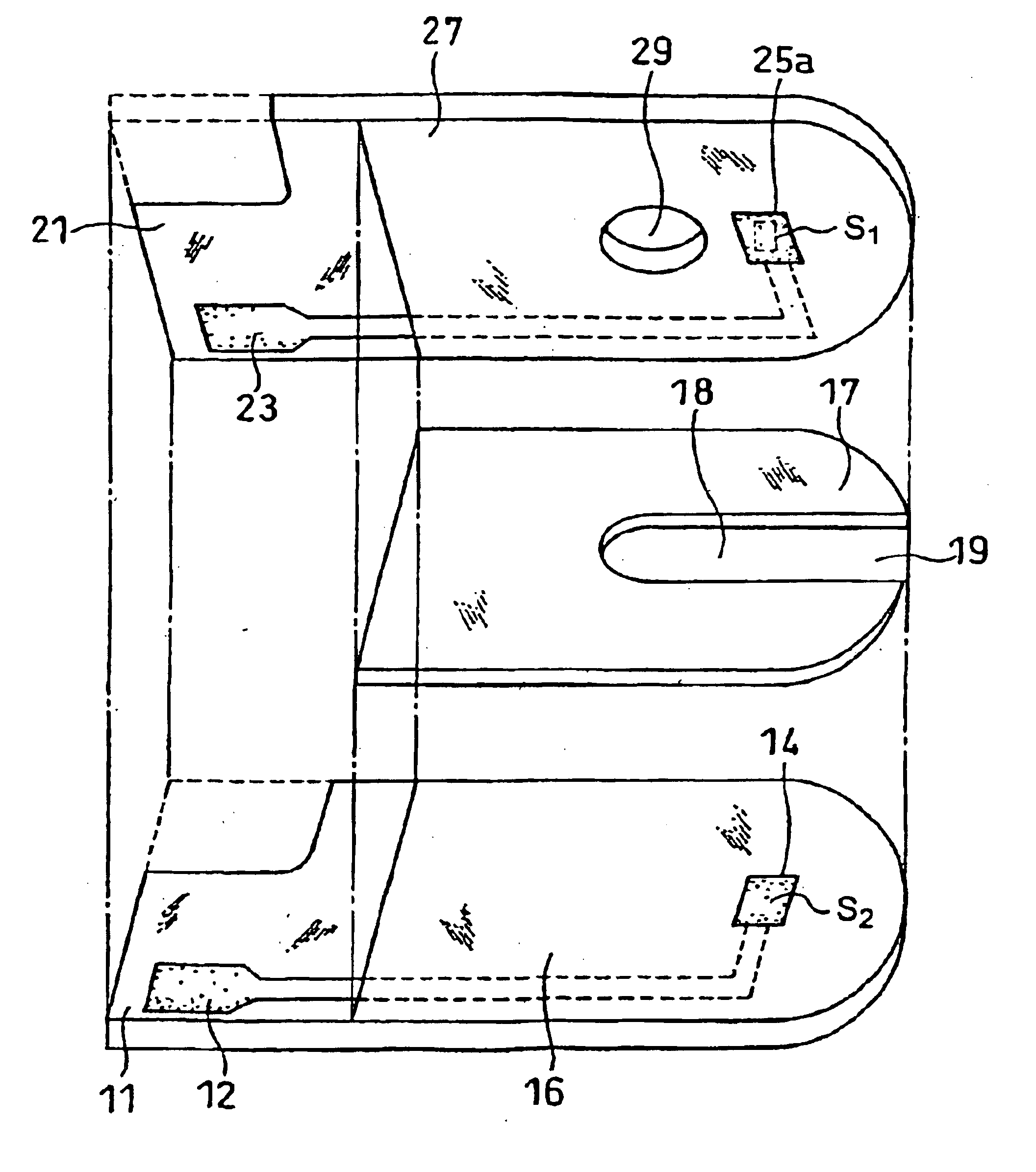
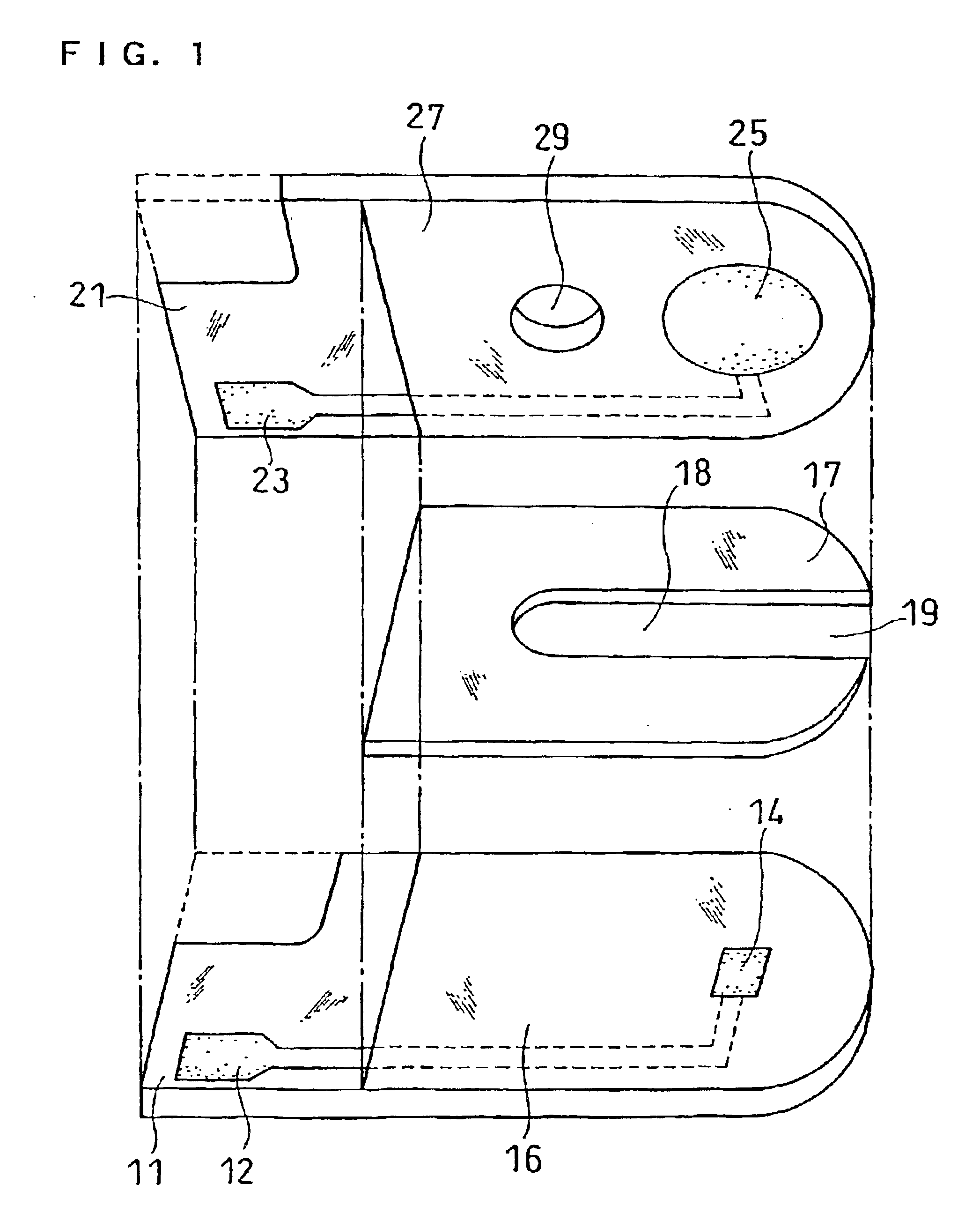
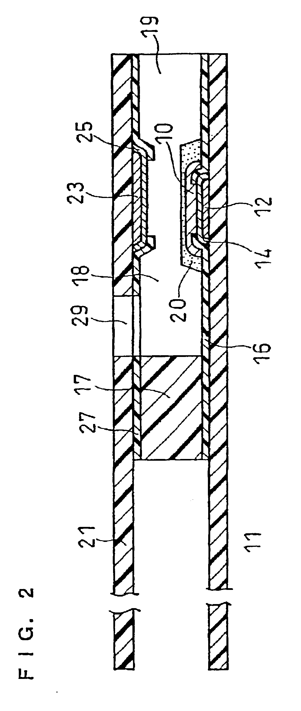
[0044]With reference to FIG. 1 and FIG. 2, this embodiment will be described. FIG. 1 is an exploded perspective view of a glucose sensor in this embodiment from which the reagent layer and surfactant layer are omitted, and FIG. 2 is a longitudinal cross-sectional view of the glucose sensor.

[0045]Numeral 11 denotes a first electrically insulating base plate made of polyethylene terephthalate. A silver paste is printed on the base plate 11 by screen printing to form a working electrode lead 12 and an electrode base, and a conductive carbon paste containing a resin binder is subsequently printed on the electrode base to form a working electrode 14. The working electrode 14 is in contact with the working electrode lead 12. Further, an insulating paste is printed on the base plate 11 to form an insulating layer 16. The insulating layer 16 covers the outer periphery of the working electrode 14 so as to keep the expose...

embodiment 2

[0051]FIG. 3 is a perspective view of a glucose sensor in this embodiment from which the reagent layer and the surfactant layer are omitted. In this embodiment, a counter electrode 25a is a rectangle similar to that of working electrode 14. The area (S1) of counter electrode 25a is the same as (solid line) or less than (broken line) that of the working electrode (S2). Other than these, this embodiment is the same as Embodiment 1.

embodiment 3

[0052]FIG. 4 is a perspective view of a glucose sensor in this embodiment from which the reagent layer and surfactant layer are omitted, and FIG. 5 is a longitudinal cross-sectional view of the glucose sensor.

[0053]This glucose sensor is produced in the following procedure.

[0054]Palladium is sputtered on an electrically insulating base plate 31 having upright pieces 37, 37 at both sides, to form a working electrode 34 and its lead 32. Next, an insulating member 36 is attached to the base plate 31 to define the working electrode 34 and a terminal portion of the lead 32 to be inserted into a measuring device. Similarly, palladium is sputtered on the inner side of a second electrically insulating base plate 41 to form a counter electrode 45 and its lead 43. Subsequently, an insulating member 47 is attached to the inner side of the base plate 41 to define the counter electrode 45 and a terminal portion of the lead 43 to be inserted into the measuring device.

[0055]Thereafter, the second ...


PUM

PropertyMeasurementUnit
areaaaaaaaaaaa
areaaaaaaaaaaa
areaaaaaaaaaaa

Abstract

A highly sensitive biosensor that uses a smaller amount of sample for measurement is described. The biosensor includes a first insulating base plate having a working electrode, a second insulating base plate having a counter electrode opposed to the working electrode, and a reagent layer containing at least an oxidoreductase. The biosensor further includes a sample supply pathway formed between the first and second insulating base plates, where the working electrode, counter electrode and reagent layer are exposed to an inside of the sample supply pathway, and the distance between the working electrode and the counter electrode is 150 μm or less.

Description

TECHNICAL FIELD[0001]The present invention relates to a biosensor for rapid and highly accurate quantification of a substrate contained in a sample.BACKGROUND ART[0002]Methods using polarimetry, colorimetry, reductimetry and a variety of chromatographies have been developed as methods for quantitative analysis of sugars such as sucrose and glucose. These methods, however, are all poorly specific to sugars and hence have poor accuracy. Among these methods, the polarimetry is simple in manipulation, but is largely affected by the temperature during the manipulation. Therefore, the polarimetry is not suitable as a method for simple quantification of sugars at home, etc. for ordinary people.[0003]Recently, various types of biosensors utilizing the specific catalytic action of enzymes have been under development.[0004]The following will describe a method of glucose quantification as one example of the method of quantifying a substrate contained in a sample.[0005]As an electrochemical met...

Claims


Application Information

Patent Timeline
Patent Type & Authority Patents(United States)
IPC IPC(8): C12Q1/00
CPCC12Q1/005G01N27/3272C12Q1/006
Inventor TANIIKE, YUKOIKEDA, SHINNANKAI, SHIRO
Owner PHC HLDG CORP
Why Eureka
Try Eureka