Rotary position measuring system

a technology of rotary position and measuring system, which is applied in the direction of measuring device, sensor output conversion, instruments, etc., to achieve the effect of high accuracy, simple and compact construction, and insensitive to unavoidable mechanical effects

Inactive Publication Date: 2005-04-26
DR JOHANNES HEIDENHAIN GMBH
View PDF36 Cites 37 Cited by
  • Summary
  • Abstract
  • Description
  • Claims
  • Application Information

AI Technical Summary

Benefits of technology

[0012]However, the position, or respectively the arrangement of the scanning unit with the light source and the detector elements is less critical with respect to the susceptibility to possible oscillations and vibrations. In accordance with the invention, this component is arranged on the side of the graduated disk, or respectively the measuring graduation structure facing away from the housing.
[0013]Therefore the result is a highly accurate rotary position measuring system based on an interferential operating principle which, on the one hand, is simply and compactly built and, on the other hand, is insensitive to unavoidable mechanical effects.

Problems solved by technology

Only in this way can the respective position measuring system become insensitive to tumbling movements of the graduated disk, which are possibly caused by oscillations of the housing or bearing tolerances.

Method used


Image

  • Rotary position measuring system
  • Rotary position measuring system
  • Rotary position measuring system

Examples


Embodiment Construction

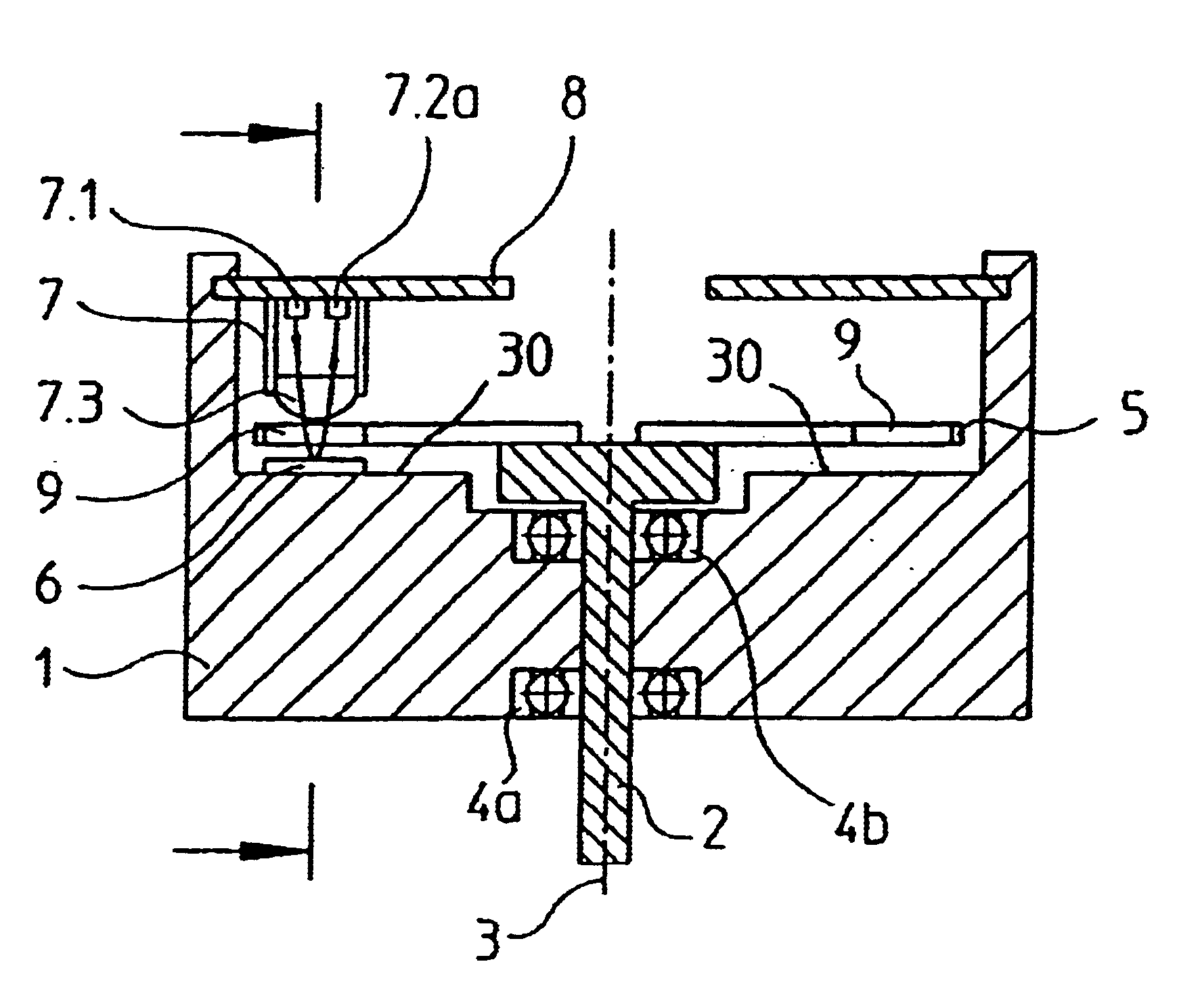
[0024]A possible embodiment of the rotary position measuring system in accordance with the invention will be described below by means of the schematic cross-sectional representation in FIG. 1. The flange of the housing 1 of the position measuring system, in which a shaft 2 is seated, rotatable around its longitudinal axis 3, can be basically recognized. In this case, the housing 1 is embodied to be cylindrical. In the exemplary embodiment represented, the shaft 2 is rotatably arranged in the housing 1 as free of friction as possible by means of two bearings 4a, 4b. In this connection it should be noted that the bearing of the shaft 2 in the housing 1 is in no way essential to the invention. The shaft 2 is in turn connected, for example via a suitable coupling, with a drive, a spindle, etc., whose rotary movement is to be respectively detected by means of the position measuring system in accordance with the invention. The latter elements are not represented for reasons of clarity. A ...


PUM


Abstract

A rotary position measuring system having a housing connected with a scanning unit having a light source that emits beams of light and a detector element. A reflection scanning graduation structure arranged directly on the housing opposite the scanning unit. A graduated disk is connected with a rotatable shaft and has a radial transmission measuring graduation structure, wherein the graduated disk is arranged so it is rotatable around an axis of symmetry in the housing so that the measuring graduation structure is located between the scanning unit and the scanning graduation structure. The beams of light emitted by the light source first reach the measuring graduation structure where they are split into a first set of diffracted partial beams of different orders and the diffracted partial beams impinge on the scanning graduation structure. A second set of diffracted partial beams of different orders results and a back-reflection of the second set of diffracted partial beams in the direction toward the measuring graduation structure results, where the second set of diffracted partial beams interfere with one another and the detection of interfering partial beams takes place by the detector element.

Description

[0001]Applicants claim, under 35 U.S.C. § 119, the benefit of priority of the filing date of Aug. 1, 1998 of a German patent application, Serial Number 198 34 860.1, filed on the aforementioned date, the entire contents of which is incorporated herein by reference. Applicants also claim, under 35 U.S.C. § 119, the benefit of priority of the filing date of May 21, 1999 of a German patent application, Serial Number 199 23 505.8, filed on the aforementioned date, the entire contents of which is incorporated herein by reference.BACKGROUND OF THE INVENTION[0002]1. Field of the Invention[0003]The invention relates to a rotary position measuring system in accordance with the interferential operating principle.[0004]2. Discussion of Related Art[0005]A so-called interferential three-grating transducer is known, for example, from EP 0 163 362 B1, or from the publication “Längen in der Ultrapräzisionstechnik messen” [Length Measuring in Ultra-Precision Technology] of A. Spiess in “Feinwerktech...

Claims


Application Information

Patent Timeline
Patent Type & Authority Patents(United States)
IPC IPC(8): G01D5/38G01D5/347G01D5/26
CPCG01D5/34715G01D5/38G01D5/3473
Inventor MICHEL, DIETERHOLZAPFEL, WOLFGANG
Owner DR JOHANNES HEIDENHAIN GMBH
Why Eureka
Try Eureka