Distributed determination of explicit rate in an ATM communication system

a communication system and explicit rate technology, applied in the field of atm communication systems, can solve the problems of reducing the processing power required on the satellite, etc., and achieve the reduction of the mass and power required in the satellite of the atm satellite communication system, reducing the processing power required, and reducing the mass and power required in the satellite.

Inactive Publication Date: 2005-04-26
OL SECURITY LIABILITY CO
View PDF14 Cites 13 Cited by
  • Summary
  • Abstract
  • Description
  • Claims
  • Application Information

AI Technical Summary

Benefits of technology

[0011]In accordance with the present invention, the mass and power required in the satellite of an ATM satellite communication system are reduced by a system design in which the calculations of the ER are carried out at a ground terminal instead of in a switch on board the satellite. This arrangement reduces the processing power required on the satellite and thus reduces the mass and power required in the satellite by shifting much of the required computation from the satellite to a ground terminal. I...

Problems solved by technology

This arrangement reduces the processing power required on the satellite and thus reduces the mass and powe...

Method used


Image

  • Distributed determination of explicit rate in an ATM communication system
  • Distributed determination of explicit rate in an ATM communication system
  • Distributed determination of explicit rate in an ATM communication system

Examples


first embodiment

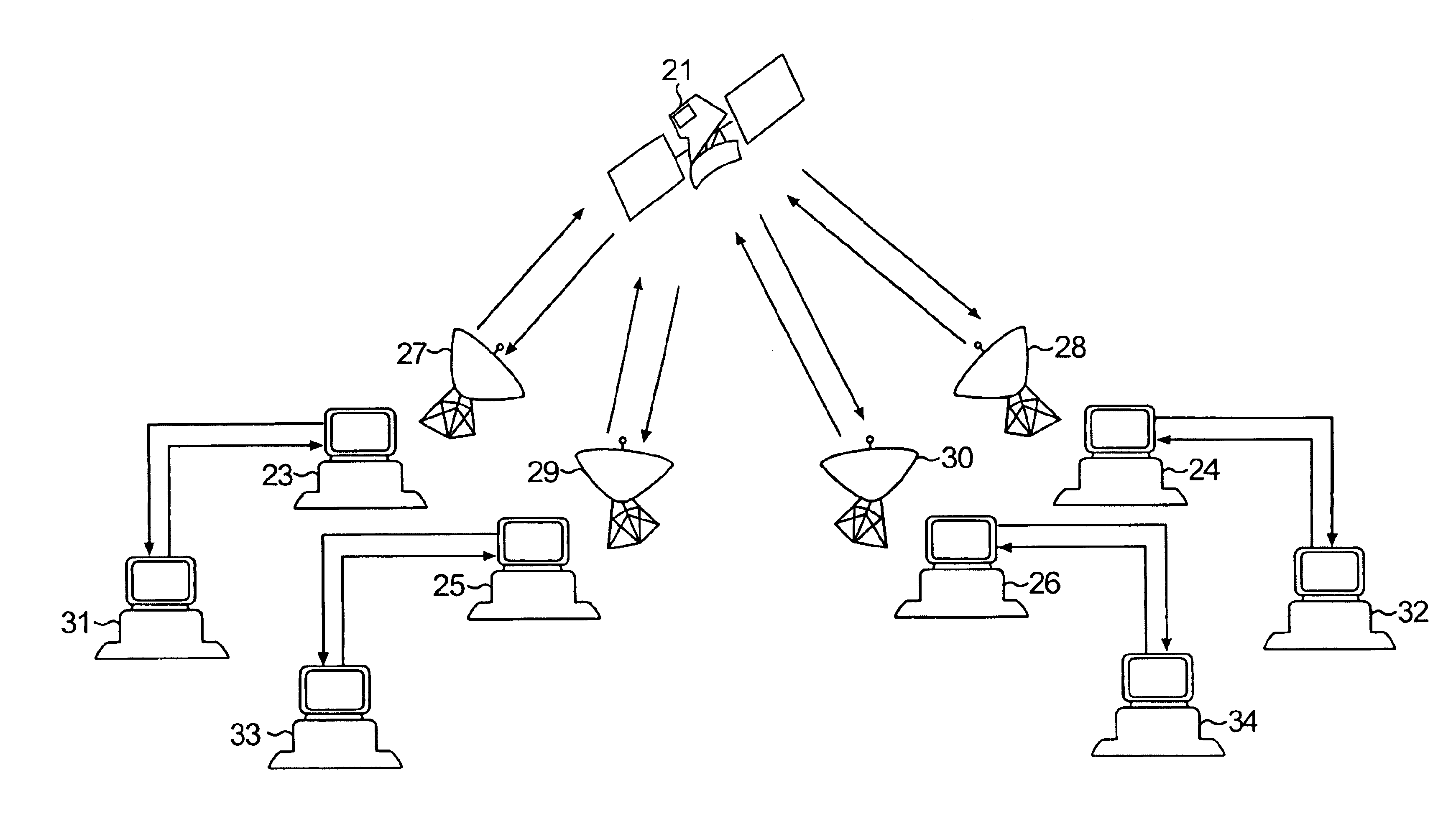
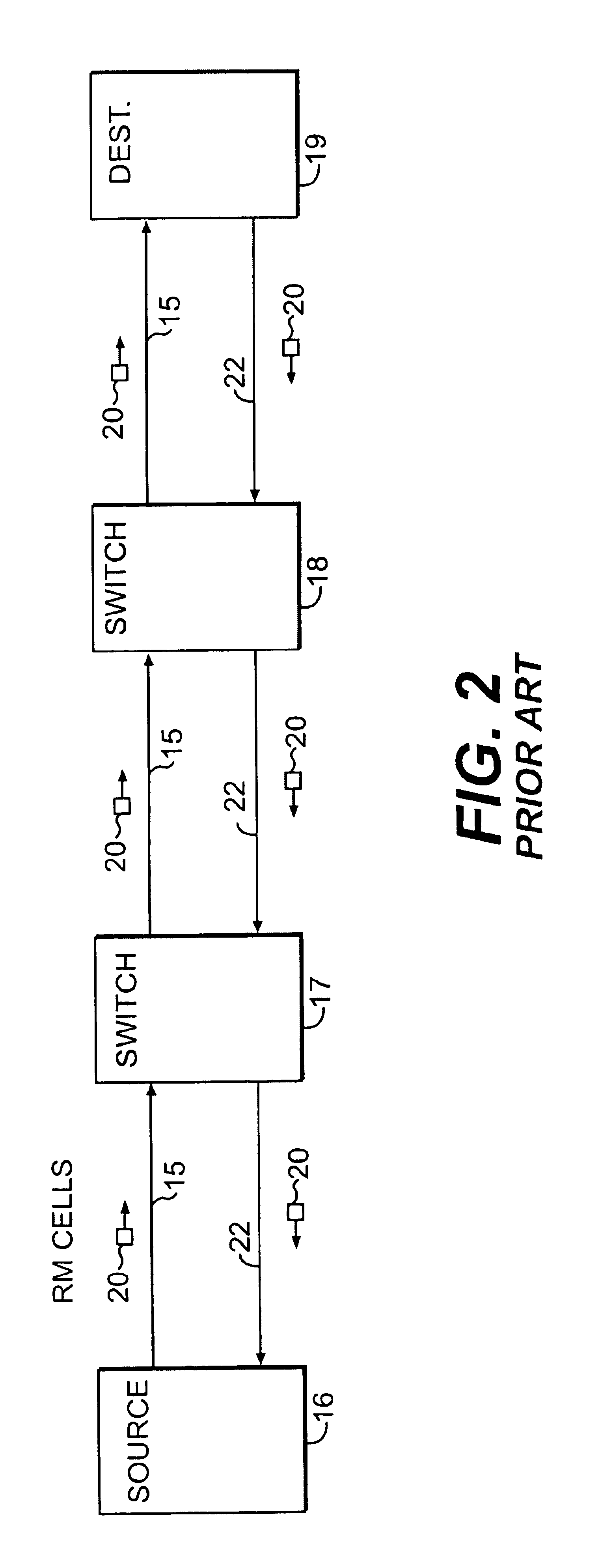
[0019]An interface in a ground station serving as a source will periodically transmit RM cells over a virtual channel to a ground station serving as a destination. The source determines a desired ER and inserts the desired ER in each RM cell. In accordance with the invention, an ER is calculated at the destination in a manner similar to the ERICA calculation of ER. The ER calculated at the destination replaces the ER in an M cell currently received at the destination, if the calculated ER is less than the ER in the RM cell. The RM cell is then transmitted back to the source of the virtual channel. The source will then use the ER in the received RM cell to govern its rate of transmission.

[0020]In order for the destination to calculate the ER, the downlink terminal has to have the CBR usage and the VBR usage in the downlink, the ABR input rate to the downlink and the number of AR type virtual channels existing in the downlink, which number will be equal to the number of currently acti...

second embodiment

[0026]In the above-described system, the satellite transmits the congestion information for a given downlink to the downlink terminals. The receiving downlink terminals then set the explicit rate in the RM cells which are then routed back to the virtual channel sources. The performance can be improved if the congestion feedback reaches the virtual channel source sooner. In accordance with the invention, the congestion parameters for each downlink are broadcast for every downlink on all of the downlinks to every uplink and downlink terminal. This enables the uplink terminals, instead of the downlink terminals, to process the congestion statistics and calculate the explicit rate to be used by each virtual channel source to determine the rate of ABR transmission by such virtual source. Ir the uplink terminal is not the source of the virtual channel, the uplink terminal transmits the calculated ER to the source in an RM cell being circulated back to the source on the associated virtual ...


PUM


Abstract

In an ATM satellite communication system, congestion parameters for the downlink from the satellite are measured in the satellite and are broadcast to the downlink terminals or to the downlink and uplink terminals linked by virtual channels extending through the satellite. At a downlink terminal or uplink terminal, the parameters broadcast from the satellite are used to calculate an explicit rate for a virtual channel in the downlink. The explicit rate calculated at the terminal is used by the source for the virtual channel to determine the rate of transmission of Available Bit Rate cells on the virtual channel.

Description

[0001]This invention claims the benefit of provisional application No. 60 / 160,302, filed Oct. 19, 1999, and provisional application No. 60 / 137,595, filed Jun. 3, 1999.[0002]This invention relates to a method and apparatus for data congestion management in an asynchronous transfer mode (ATM) communication system and more particularly to a method and apparatus for data congestion management in an ATM satellite communication system with processing and switching on board the satellite.BACKGROUND OF THE INVENTION[0003]In an ATM communication system, data is communicated between terminals over virtual channels in data packets called cells. ATM communication systems are described in the textbook entitled ATM Theory and Application by David McDysan and Darren Spohn, 1999, published by McGraw-Hill. This textbook is hereby incorporated by reference. As shown in FIG. 1, which schematically illustrates a typical ATM communication system, the system comprises a large number of stations or termin...

Claims


Application Information

Patent Timeline
IPC IPC(8): H04J3/14H04J1/16H04J1/00H04L12/56
CPCH04L12/5601H04L2012/5636H04L2012/5635H04L2012/5608
Inventor SHVODIAN, WILLIAM M.
Owner OL SECURITY LIABILITY CO
Why Eureka
Try Eureka