
Eye gaze control of dynamic information presentation

a dynamic information and display screen technology, applied in the direction of mechanical pattern conversion, cathode-ray tube indicators, instruments, etc., can solve the problems of inconvenient adjustment of eye movements, difficult interaction, frustrating, etc., and people are not accustomed to changing their visual environmen

Inactive Publication Date: 2005-04-26
TOBII TECH AB
View PDF9 Cites 104 Cited by
  • Summary
  • Abstract
  • Description
  • Claims
  • Application Information

AI Technical Summary

Benefits of technology

This approach allows for natural and efficient navigation through scrollable information, automatically adjusting the scroll rate and direction to match the user's reading speed, enhancing usability for individuals unable to use conventional input devices.

Problems solved by technology

While eye trackers can enable human-computer interaction using only the eyes, there are many reasons that such interaction can be difficult, frustrating, and tiresome.
First, people do not normally consciously control their eye movements.
Furthermore, people are not accustomed to changing their visual environment simply by looking at it.
Finally, eye gaze information is limited to cursor or screen position, which leads to very cumbersome styles of interaction.
However, this results in an unnatural, slow, and cumbersome means of controlling the computer.
Reading text and navigating through information on computer screens can be difficult even when using conventional input devices and interaction idioms, like dragging the tab on a window scroll bar.
This is made even more difficult when the user is unable to use conventional devices and must use alternatives, like eye tracking systems.

Method used


Image

  • Eye gaze control of dynamic information presentation
  • Eye gaze control of dynamic information presentation
  • Eye gaze control of dynamic information presentation

Examples


Embodiment Construction

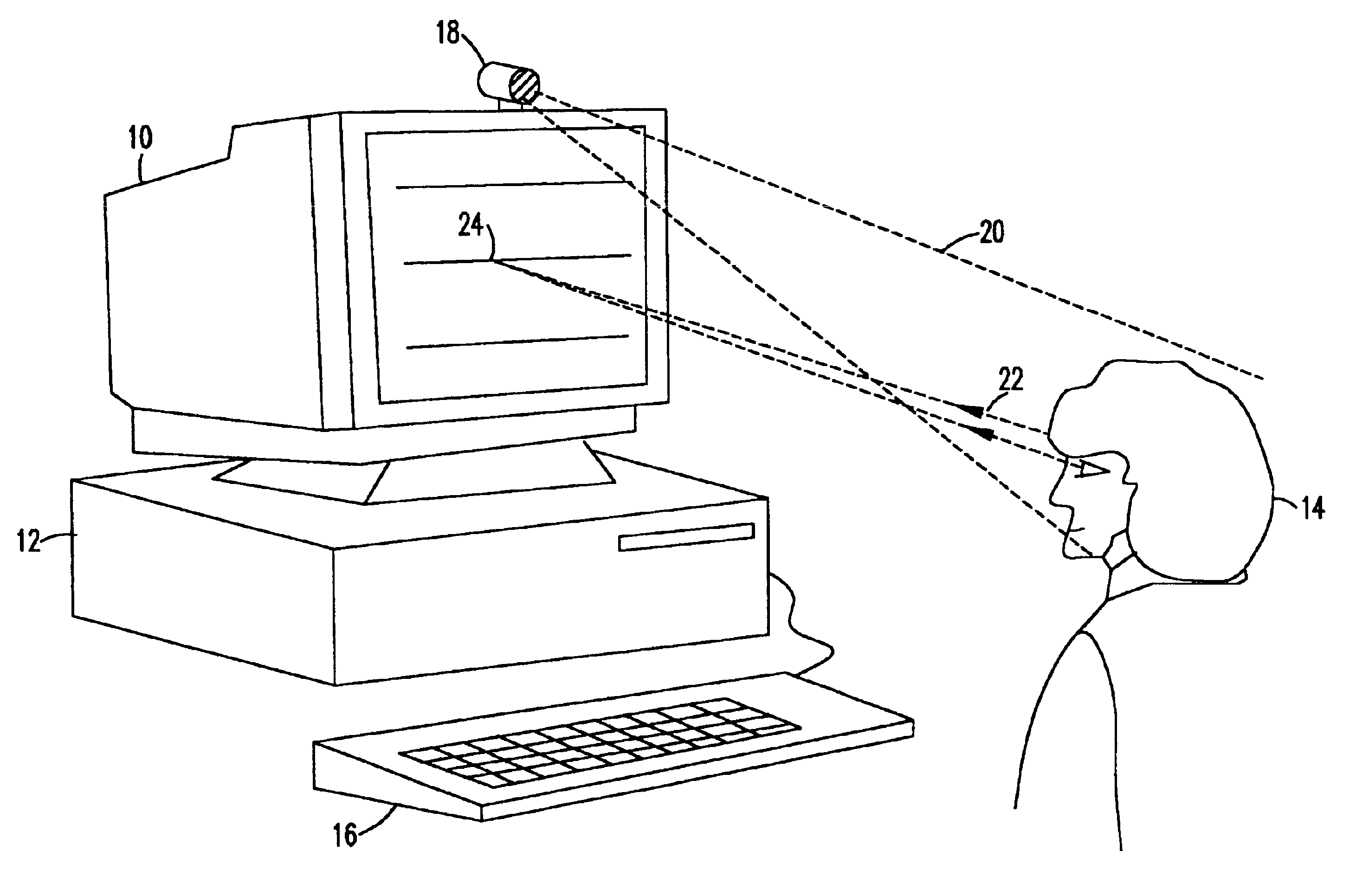
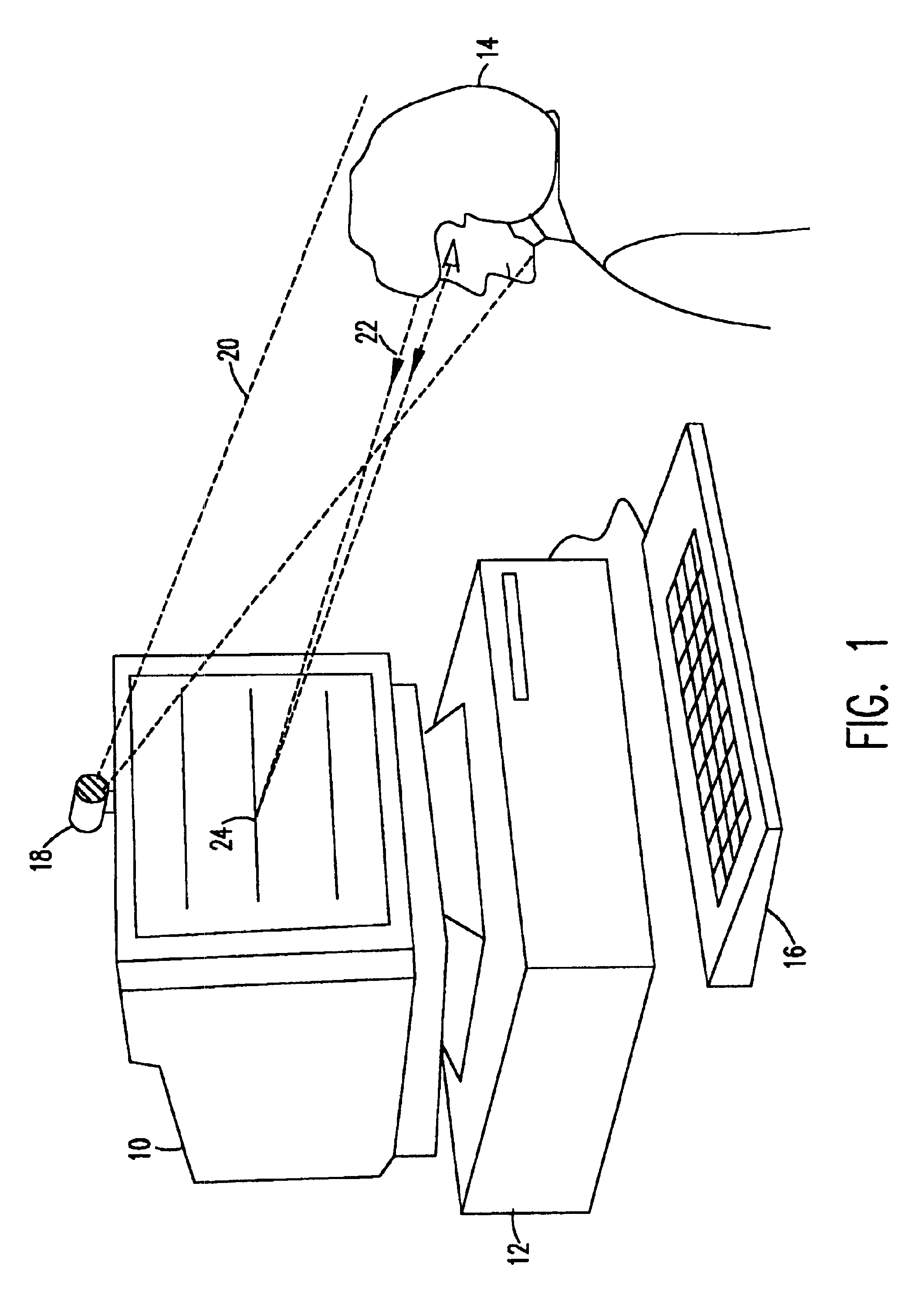
[0015]Referring now to the drawings, and more particularly to FIG. 1 there is shown a typical set up for the present invention. A display monitor 10 is connected to a computer 12 and positioned in front of a user 14. Traditional input devices such as a keyboard 16 or mouse (not shown) may also be present. However, in certain situations, the user may have physical constraints that render them unable to use traditional input devices. Therefore, the present invention provides an alternative to these traditional devices and would be useful for any individual capable of moving his or her eyes, including a quadriplegic or similarly disabled person.

[0016]In particular, an eye gaze tracker 18 is mounted and aimed such that the user's eyes 22 are in its field of vision 20. Suitable eye tracking devices or cameras are well known in the art. The purpose of eye gaze trackers, also called eye trackers, is to determine where an individual is looking. The primary use of the technology is as an inp...


PUM


Abstract

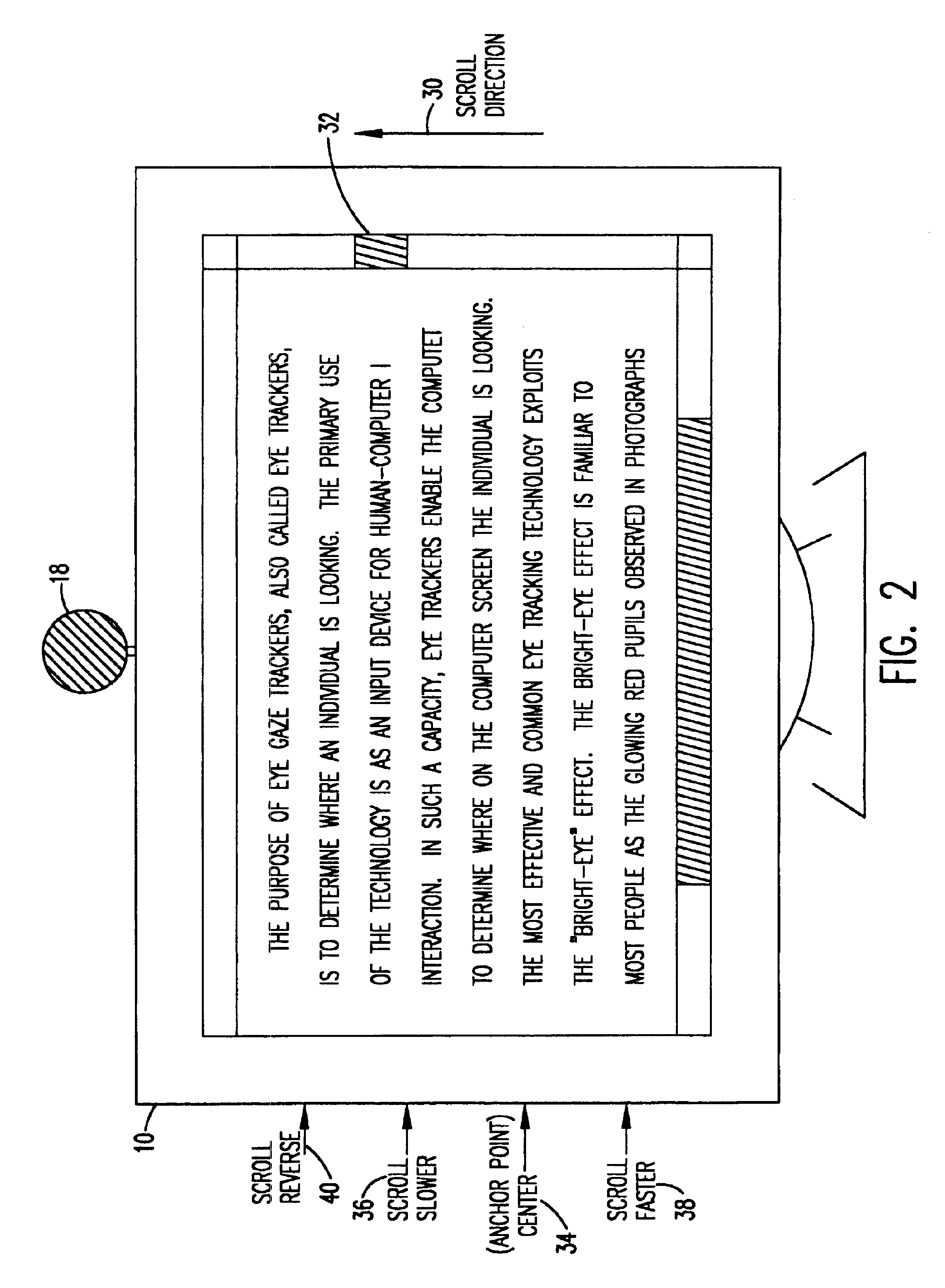
A hands-free system uses eye gaze information from an eye gaze tracking device to continuously control the rate and direction of scrollable information presented on a display in a natural manner. Initially, images begin scrolling on the display at an initial rate. An eye tracking device is used to determine the area on the display that the user is gazing. If the gaze remains fixed near an anchor position, this indicates that the images are scrolling at a comfortable speed for the user to read the information. However, if the gaze begins to drift towards the side of the display where information is appearing, the scroll rate is increased since this indicates that the text is scrolling too slowly. Conversely, if the user's gaze is detected to move toward the side of the screen where information is disappearing, the scroll rate is decreased since this indicates that the user is falling behind. If the user's gaze gets too close to the side of the screen where information is disappearing the scroll direction may be reversed.

Description

BACKGROUND OF THE INVENTION[0001]1. Field of the Invention[0002]The present invention generally relates to a system for scrolling a screen and, more particularly, to a system for scrolling an image on a computer display screen based on eye movements.[0003]2. Description of the Related Art[0004]Eye tracking systems can determine where on a computer screen the user is looking and they have been used as the primary input device of computers, replacing both the keyboard and the mouse. Thus, such systems are able to control all processes of a computer that do not require response times that are too short to be provided via eye movements and software constraints. Since these systems do not require any force or the use of any movements other than the eyes, they are appealing for use by people who are unable to use conventional devices.[0005]While eye trackers can enable human-computer interaction using only the eyes, there are many reasons that such interaction can be difficult, frustratin...

Claims


Application Information

Patent Timeline
Patent Type & Authority Patents(United States)
IPC IPC(8): G06F3/00G06F3/01
CPCG06F3/013G06F3/0485
Inventor PECK, CHARLES C.MACKAY, JOHN D.
Owner TOBII TECH AB
Learn More