Fuel injector and operating method therefor

a fuel injector and fuel technology, applied in the direction of piezoelectric/magnetostrictive element fuel injection, spray nozzles, movable spraying apparatus, etc., can solve the problems of reducing the effective operational lifespan, de-energising the injector system, and a large percentage of its operating life, etc., to achieve large actuator displacement, reduce one, and large differential voltage change

Inactive Publication Date: 2009-07-23
DELPHI TECH IP LTD
View PDF6 Cites 8 Cited by
  • Summary
  • Abstract
  • Description
  • Claims
  • Application Information

AI Technical Summary

Benefits of technology

[0015]In broad terms, the invention provides a fuel injector and a drive strategy for a fuel injector, which achieves some of the benefits of de-energise to inject fuel injector designs, while reducing one or more disadvantages associated with such known systems. In part, the invention further provides a fuel injector and a drive strategy for a fuel injector, that provides the advantages of energise to inject fuel injectors, but without the limitations on the range of differential voltages that can be employed. In one respect, the invention provides a method for operating a piezoelectric-actuated fuel injector, which allows large differential voltage changes and, hence, large actuator displacements, while avoiding the need to maintain large positive differential voltages across the actuator for the majority of its operational life. More specifically, the invention relates to a drive strategy for a piezoelectric-actuated energise to inject injector, which permits negative voltages to be used to increase piezoelectric stack displacement, but without a significant risk of expediting the depolarisation of the actuator. In this way, one or more advantages over the prior art may be achieved, for example: a bipolar mode of operation can be employed in an energise to inject injector, to increase actuator displacement and valve needle lift; since it is not necessary to maintain the actuator at a negative voltage for a prolonged period of time, the actuator is not rapidly depolarised; since the actuator is not maintained at a large positive voltage for the majority of its operational life, it is not so prone to piezoelectric degradation; actuator operational lifespan can be increased; energy efficiency can be increased.

Problems solved by technology

However, de-energise to inject systems suffer the disadvantage that for the majority (approximately 95%) of its operating life, i.e. while the injector is not injecting, the piezoelectric actuator stack must be maintained at a high positive differential voltage (e.g. 200 V).
If moisture, for example, is present within the actuator, this high positive voltage can cause electrochemical degradation of the piezoelectric material, resulting, after time, in a short circuit failure and, hence, a reduced effective operational lifespan.
This type of prior art injector, however, cannot be run with significant bipolar voltages, since maintaining a negative voltage on the piezoelectric actuator for 95% of its operational life would result in actuator depolarisation, causing high electrical losses plus reduced actuator life and performance.
Accordingly, prior art energise to inject piezoelectric-actuated fuel injectors do not so readily allow for large actuator displacements, which can be particularly disadvantageous where large fuel injections are required.
Another factor to consider is that prior art piezoelectric injectors require a relatively large and expensive piezoelectric actuator to provide the energy needed to lift the needle.
Coupled with the fact that the amount of needle lift is limited by the capabilities of the actuator (even if a hydraulic amplifier is used to try to alleviate this problem), and any injector drive system limitations; the loss of the bipolar mode of operation in prior art energise to inject injectors severely limits the effectiveness of these injectors, particularly as injector nozzle flow requirements and fuel pressures increase.

Method used


Image

  • Fuel injector and operating method therefor
  • Fuel injector and operating method therefor
  • Fuel injector and operating method therefor

Examples


Embodiment Construction

[0076]Before describing the specific embodiments of the invention as set forth in the figures, the following definitions are provided.

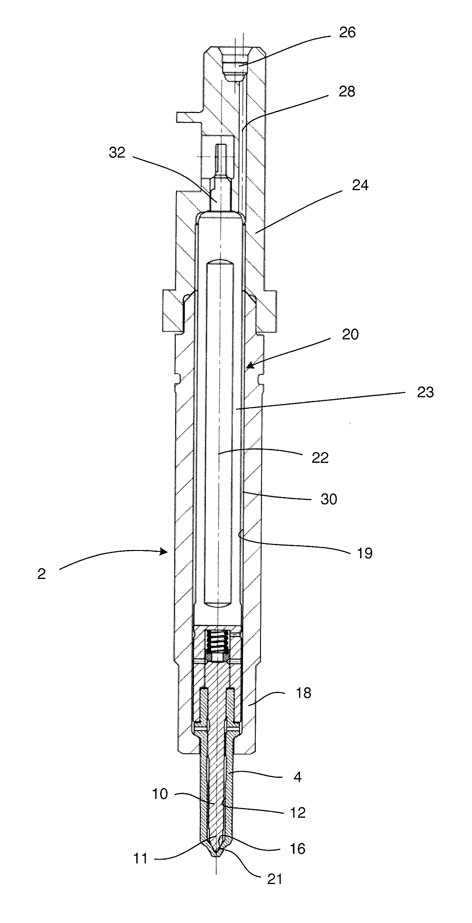
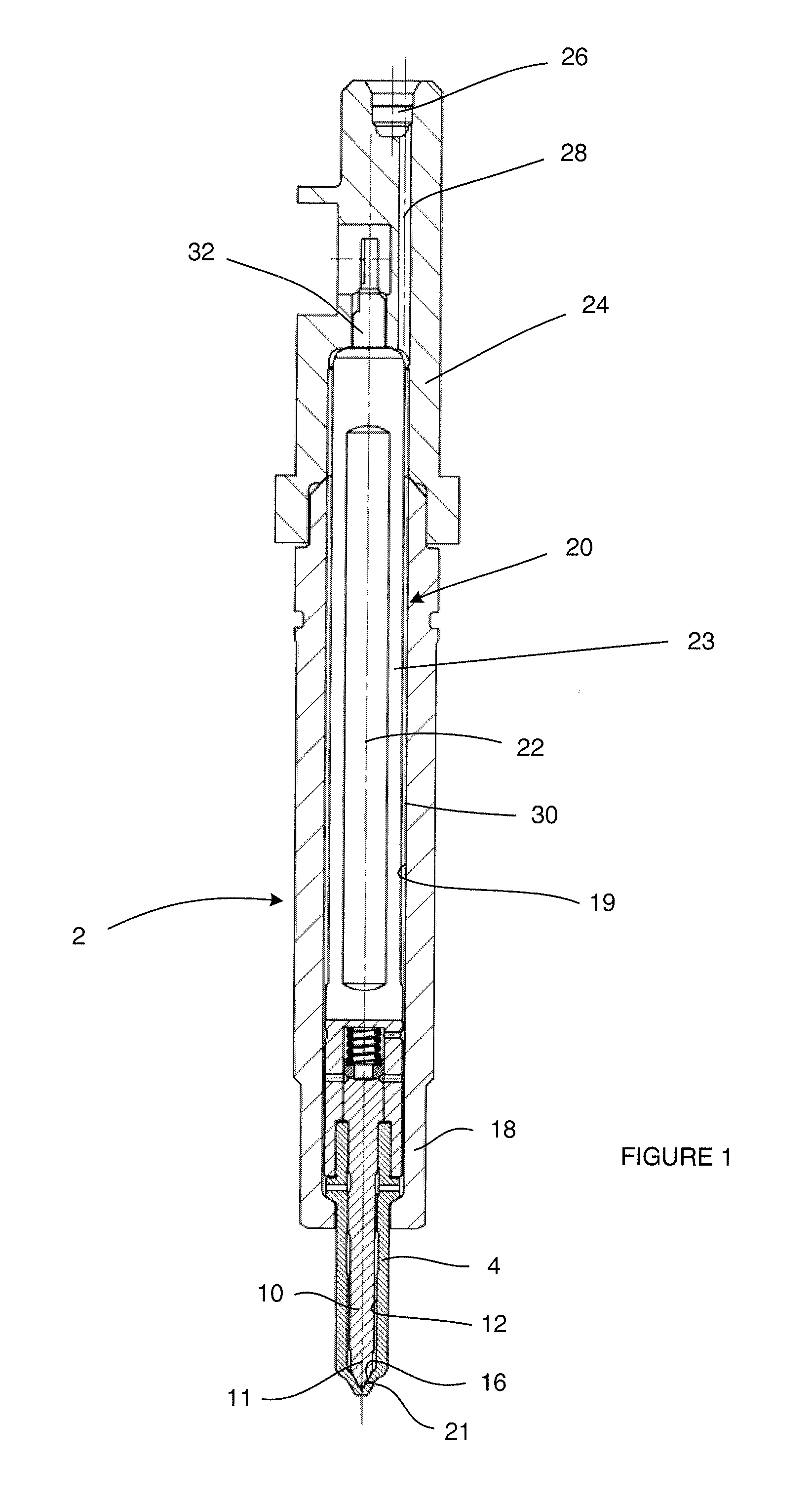
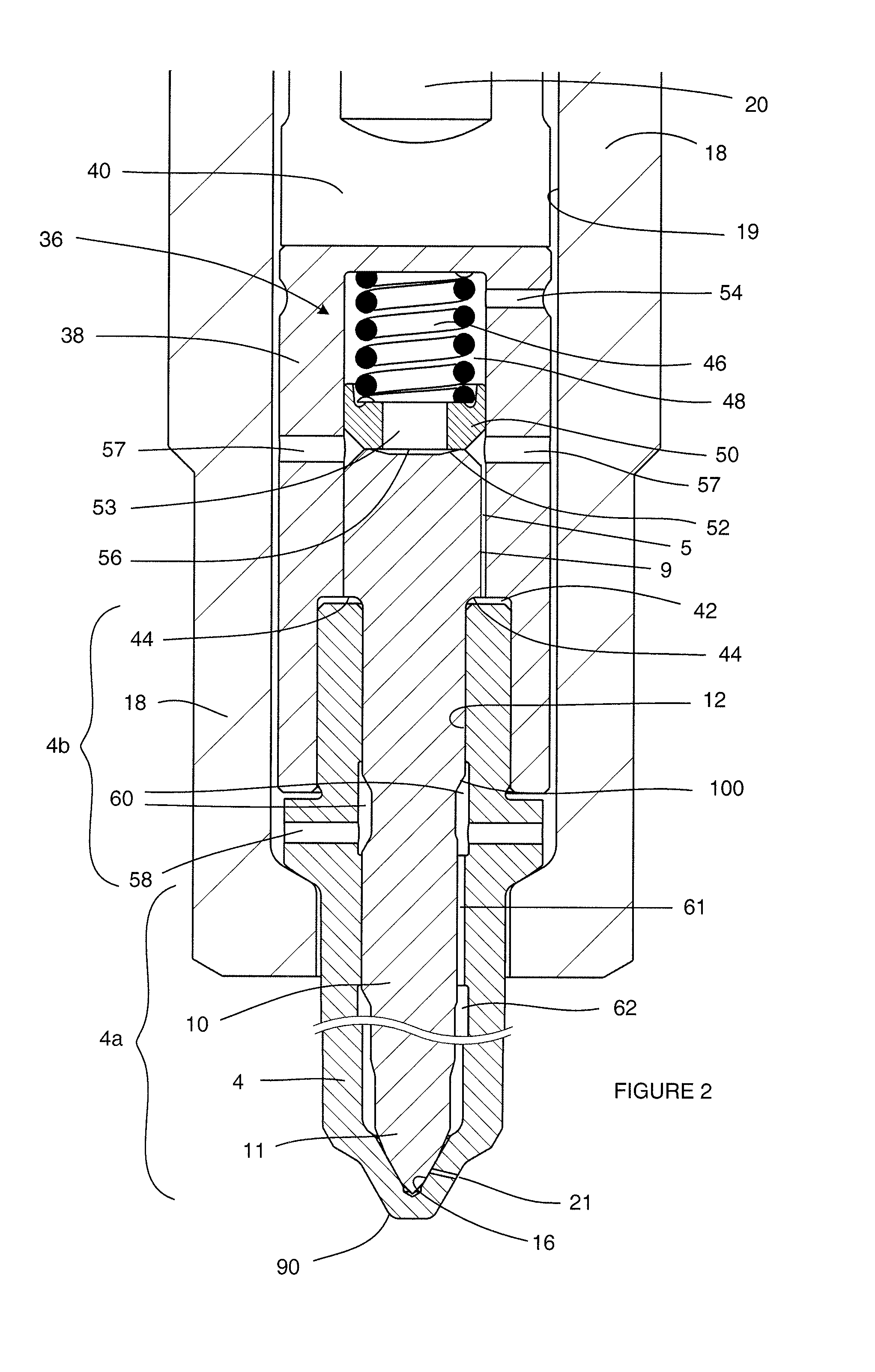
[0077]As used herein, it will be understood that by the term “nozzle outlets” it is meant the holes (or apertures) through which fuel is injected from the injection nozzle of the fuel injector and into an associated engine cylinder (in use), which may also be referred to as injection holes, spray holes or similar terms known in the art. By “a set of nozzle outlets” it is meant the one or more nozzle outlets through which fuel is injected when a particular valve needle is disengaged from its associated valve needle seat (or seating region). Thus, in the context of this invention, a valve needle is typically associated with a seating region and an associated “set” of nozzle outlets. It is possible for a valve needle to have more than one associated seating region (e.g. two). In such a case, each seating region is associated with a set of nozzle outlets ...


PUM


Abstract

A method of operating a fuel injector having a piezoelectric actuator for controlling movement of an injector valve needle comprises: (a) prior to an initial fuel injection event, reducing the voltage across the actuator at an initial rate so as to de-energise the actuator; (b) increasing the voltage across the actuator at a first rate in order to initiate an initial fuel injection event of a first fuel injection sequence; and (c) reducing the voltage across the actuator at a second rate in order to terminate the initial fuel injection event. The method may further comprise the step of: (d) increasing the voltage across the actuator at a third rate, which is lower than the first rate, so as to de-energise the actuator but without initiating an injection event, once the initial fuel injection event has terminated and before a subsequent fuel injection event is initiated. The method can be employed particularly to improve actuator lifespan, operating efficiency and/or performance in an energize to inject fuel injector.

Description

FIELD OF THE INVENTION[0001]The invention relates to a fuel injector for use in the delivery of fuel to a combustion space of an internal combustion engine. In particular, the invention relates to a piezoelectric-actuated fuel injector of the energise to inject type, and to a method of operating it to allow large piezoelectric stroke lengths while preserving actuator performance and / or lifespan.BACKGROUND OF THE INVENTION[0002]In an internal combustion engine, it is known for a fuel pump to supply fuel to a high-pressure accumulator (or common rail), from which it is delivered into each cylinder of the engine by means of a dedicated fuel injector. Typically, a fuel injector has an injection nozzle which is received within a bore provided in a cylinder head of the cylinder; and a valve needle which is actuated to control the release of high-pressure fuel into the cylinder from spray holes provided in the nozzle.[0003]It is known to provide a fuel injector for an automotive engine wit...

Claims


Application Information

Patent Timeline
Patent Type & Authority Applications(United States)
IPC IPC(8): B05B1/08
CPCF02D41/2096F02D2041/2051F02D2041/2058F02M2200/705F02M2200/21F02M2200/704F02M51/0603
Inventor COOKE, MICHAEL PETER
Owner DELPHI TECH IP LTD
Why Eureka
Try Eureka