Ratchet wrench having a pivotal head

a ratchet wrench and pivotal head technology, applied in the field of ratchet wrenches, can solve the problems of limited application of the conventional ratchet wrench, and achieve the effect of improving applicability

Inactive Publication Date: 2005-05-03
LEE CHANG CHUAN
View PDF6 Cites 29 Cited by
  • Summary
  • Abstract
  • Description
  • Claims
  • Application Information

AI Technical Summary

Benefits of technology

[0006]The primary object of the present invention is to provide a ratchet wrench having a pivotal head, wherein a ratchet head is coupled to a handle of the ratchet wrench in a manner that the operational angle of the ratchet head is adjustable, and thus the ratchet wrench in accordance with the present invention is improved in applicability.
[0007]In accordance with one aspect of the respect of the present invention, there is provided with a ratchet wrench having a pivotal head, which generally includes a handle, an elastic plate, an elastic block and a pivotal head. Wherein the handle is defined with a slot at an end thereof, the elastic block is defined at an end thereof with an engaging portion, and at another end thereof is formed with a notch for the reception of the elastic plate. With the help of the elastic plate, the elastic block is movably received in the slot of the handle of the ratchet wrench. At end of the pivotal head is formed with a coupling portion that is to be received in the slot of the handle, so as to engage with the engaging portion of the elastic block. By such arrangements, the ratchet head of the wrench can change the operational angle relative to the handle, so as to improve the applicability of the ratchet wrench.

Problems solved by technology

However, since the ratchet wheel, the locking block and the elastic element are disposed at an end of the integral-formed ratchet wrench, a handle of the ratchet wrench is not foldable according to special needs, and as a result that an operational angle of the ratchet wrench is not adjustable either, therefore, the applicability of the conventional ratchet wrench is limited.

Method used


Image

  • Ratchet wrench having a pivotal head
  • Ratchet wrench having a pivotal head
  • Ratchet wrench having a pivotal head

Examples


Embodiment Construction

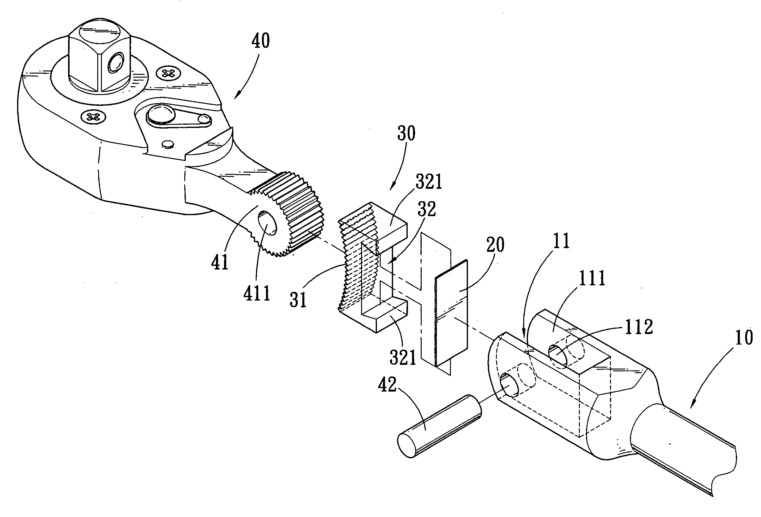
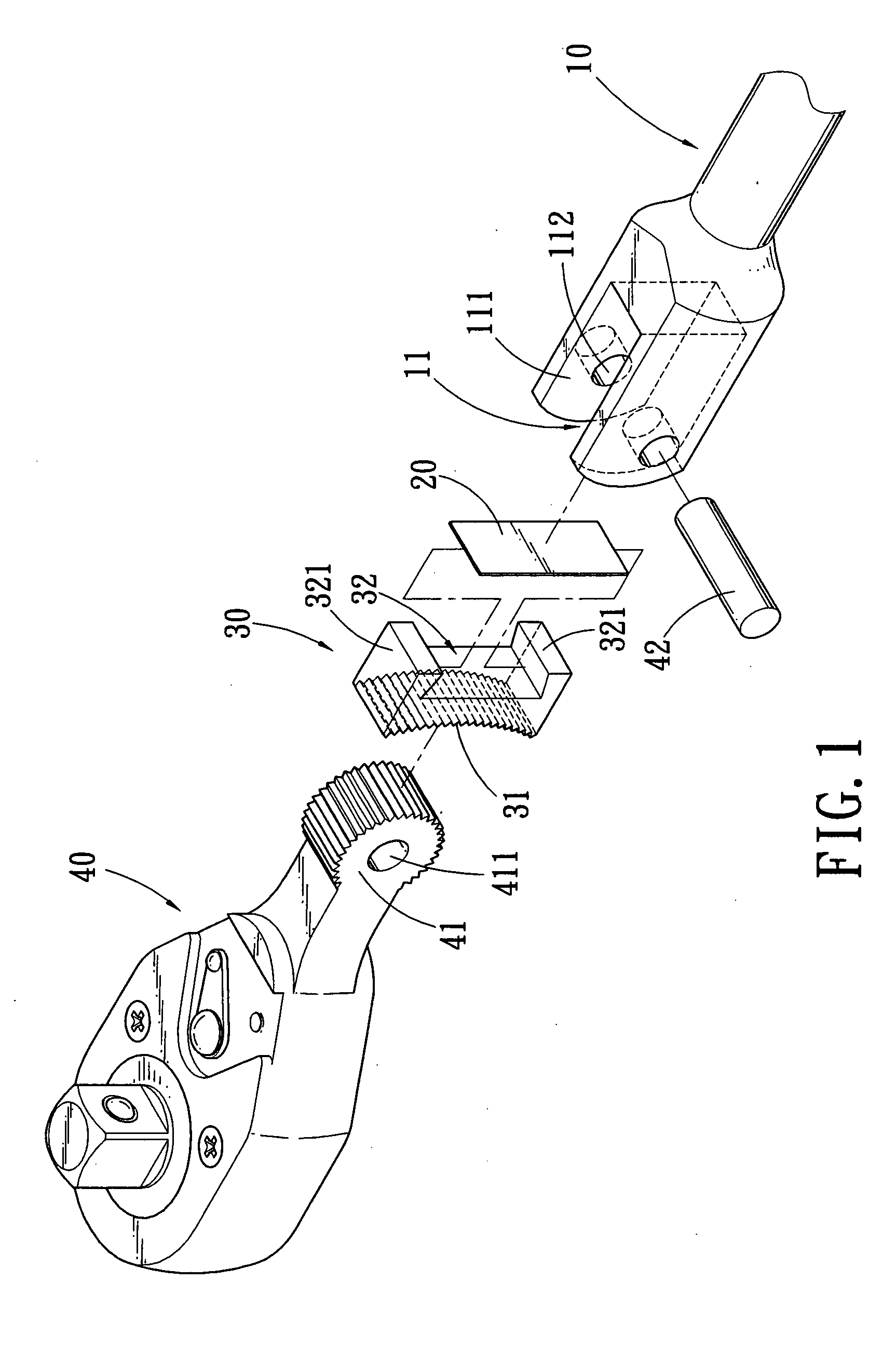
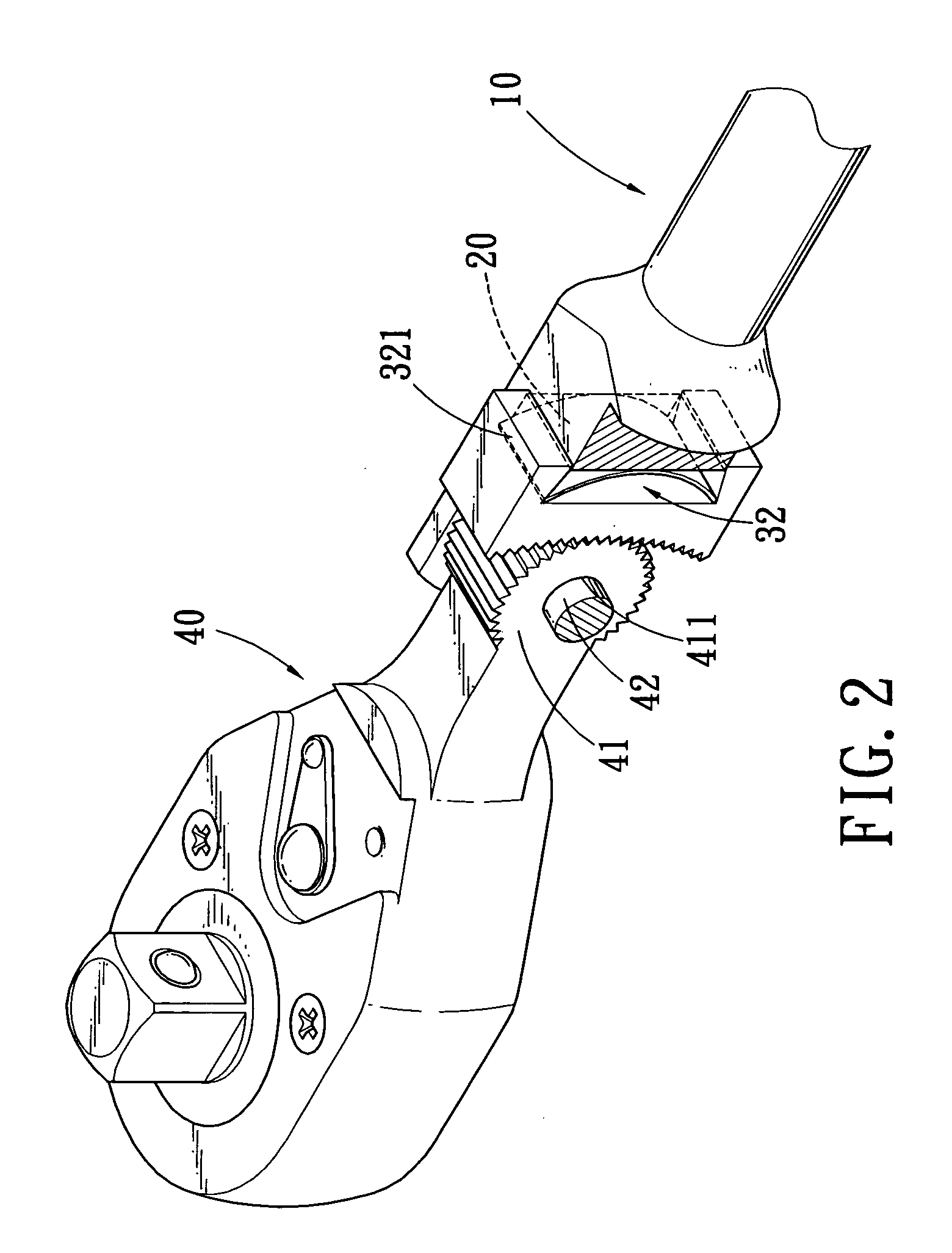
[0014]Referring to FIGS. 1–3, wherein a ratchet wrench having a pivotal head in accordance with a preferred embodiment of the present invention is shown and generally comprising a handle 10, an elastic plate 20, an elastic block 30 and a ratchet head 40.

[0015]The handle 10 is provided at a first end thereof with a ‘U’-shaped slot 11, on both opposite sides 111 of the slot 11 a through hole 112 is defined, whereas a second end of the handle 10 is provided for a user's grip.

[0016]The elastic plate 20 is a bendable piece to be received in the slot 11 of the handle 10.

[0017]The elastic block 30 is provided at a first end thereof with an engaging portion 31 with threads, whereas at a second end of the elastic block 30 is defined with a ‘U’-shaped notch 32. Wherein width of a mouth of the notch 32 is minor than that of a bottom of the notch 32, such that internal surface of sidewall 321 of the notch 32 is inclined. The elastic plate 20 engages in the notch 32 with both ends abutting agai...


PUM


Abstract

The present invention relates to a ratchet wrench having a pivotal head, which generally includes a handle, an elastic plate, an elastic block and a pivotal head. Wherein the handle is defined with a slot at an end thereof, the elastic block is defined at an end thereof with an engaging portion, and at another end thereof is formed with a notch for the reception of the elastic plate. With the help of the elastic plate, the elastic block is movably received in the slot of the handle of the ratchet wrench. At end of the pivotal head is formed with a coupling portion which is to be received in the slot of the handle, so as to engage with the engaging portion of the elastic block. By such arrangements, the ratchet head of the wrench can change the operational angle relative to the handle, so as to improve the applicability of the ratchet wrench.

Description

BACKGROUND OF THE INVENTION[0001]1. Field of the Invention[0002]The present invention relates to a ratchet wrench, and more particularly to a ratchet wrench that has a pivotal head.[0003]2. Description of the Prior Arts[0004]A conventional ratchet wrench, at an end of which is generally provided with a ratchet wheel, a locking block and an elastic element, the ratchet wrench is processed with a capability of changing rotation direction during operation, and thus it is more convenient for the ratchet wrench to screw the object to be operated. However, since the ratchet wheel, the locking block and the elastic element are disposed at an end of the integral-formed ratchet wrench, a handle of the ratchet wrench is not foldable according to special needs, and as a result that an operational angle of the ratchet wrench is not adjustable either, therefore, the applicability of the conventional ratchet wrench is limited.[0005]The present invention has arisen to mitigate and / or obviate the a...

Claims


Application Information

Patent Timeline
Patent Type & Authority Patents(United States)
IPC IPC(8): B25B13/00B25B13/46B25B23/00B25G1/06
CPCB25B13/461B25G1/063B25B23/0028
Inventor LEE, CHANG-CHUAN
Owner LEE CHANG CHUAN
Why Eureka
Try Eureka