Hanging scaffold support

a technology for scaffolding and supports, applied in the direction of scaffold accessories, machine supports, building scaffolds, etc., can solve the problems of limited utility of ladders, impracticality of scaffolding built from the ground up, and heavy scaffolding, so as to facilitate the insertion of hangers, prevent shifting or twisting, and facilitate the securement of working surfaces

Inactive Publication Date: 2005-05-03
JDPR INVESTMENTS LLC
View PDF47 Cites 32 Cited by
  • Summary
  • Abstract
  • Description
  • Claims
  • Application Information

AI Technical Summary

Benefits of technology

[0016]A hanger may secure the scaffold support to a wall or window sill. A lateral beam may project from the leg and rest on a support structure, such as the top surface or top plate of a wall or a window sill, during operation of the scaffold support. A stop may secure to the lateral beam and capture a supporting structure (e.g. wall) between the stop and the leg to prevent accidental slipping or release of the lateral beam from a support structure.
[0018]Alternative embodiments may position the lateral beam beneath a support structure. A spacer may secure a loading structure to the lateral beam, spaced apart therefrom. During normal operation, a support structure may be positioned between the lateral beam and the support structure. The spacer may secure at various positions along the lateral beam to further capture a support structure between the spacer and portions of the leg extending above a lateral beam.
[0019]In some modes of operation of a hanger, the hanger is removed from the leg in order to facilitate insertion of the hanger where Frieze blocks, or other roofing materials, hinder its insertion. A removable hanger may be inserted from the inside of a building with the leg positioned on the outside. An elongate coupler may secure to the lateral beam and be sized to fit between a gap between a Frieze block and a support structure. During operation, the coupler may be lowered through the gap and secured to the leg without requiring that the stop and lateral beam pass through the gap.
[0020]Structures may be provided to facilitate securement of a working surface to a scaffold support. A catch may secure at various points along the foot to secure an edge of the deck to prevent shifting or twisting. The catch may slidably secure to the foot and have a lock to fix the position of the catch relative to the foot. In some embodiments the catch is a notch positioned to engage a flange, or the like, forming part of a deck.
[0021]An edge of a deck may also be secured by an eye. The eye may have an aperture sized to receive a tether or cable for securing the apparatus against theft. A portion of the eye may extend over an edge of a deck (or flange of a beam of the deck) to prevent the edge from rising during use. In some embodiments, a scaffold support may be provided with both a catch and an eye. A deck may be positioned between the catch and the eye to restrain both edges of the deck and prevent shifting, tilting, and rotation of the deck. The adjustability of the catch may allow the deck to be laid on the foot and the catch subsequently brought into position to engage the deck. A second eye may be provided at an upper end of a leg to receive a rope, or the like, for raising and lowering of the scaffold support.

Problems solved by technology

Many feet above ground level, scaffolding built from the ground up becomes impractical.
Scaffolding presents several problems.
To provide proper structural strength, scaffolding is typically quite heavy.
Ladders are limited in their utility.
Ladders may not be positionable readily both inside and outside the envelope of a building at all stages of construction where scaffolding may be useful or required.
The weight, bulk, manpower, lack of flexibility in application, awkwardness in working indoors or in semi-finished areas, and the like add to the difficulty and expense of using conventional scaffolding.

Method used


Image

  • Hanging scaffold support
  • Hanging scaffold support
  • Hanging scaffold support

Examples


Embodiment Construction

[0036]It will be readily understood that the components of the present invention, as generally described and illustrated in the Figures herein, could be arranged and designed in a wide variety of different configurations. Thus, the following more detailed description of the embodiments of the system and method of the present invention, is not intended to limit the scope of the invention. The scope of the invention is as broad as claimed herein. The illustrations are merely representative of certain, presently preferred embodiments of the invention. Presently preferred embodiments of the invention will be best understood by reference to the drawings, wherein like parts are designated by like numerals throughout.

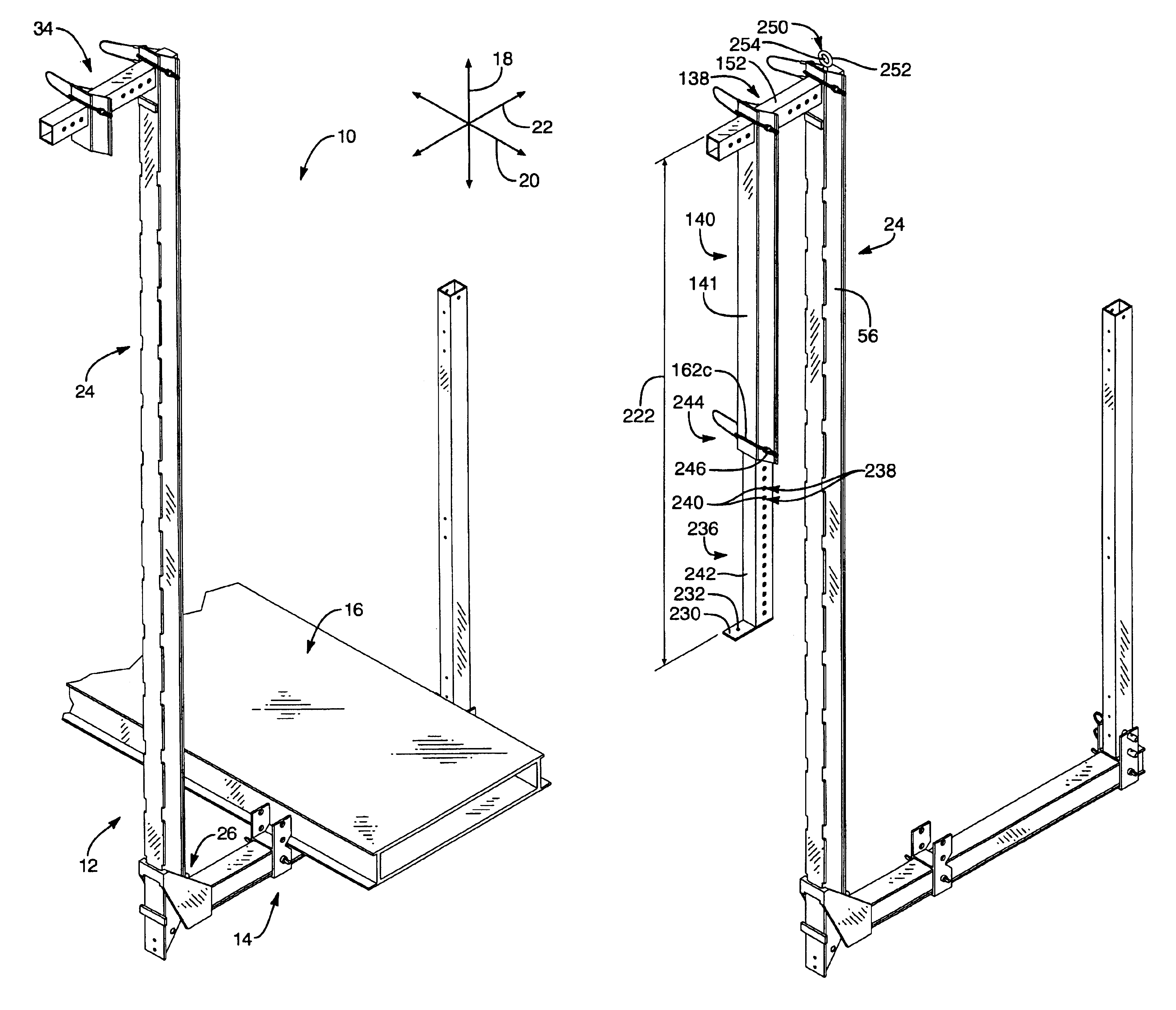
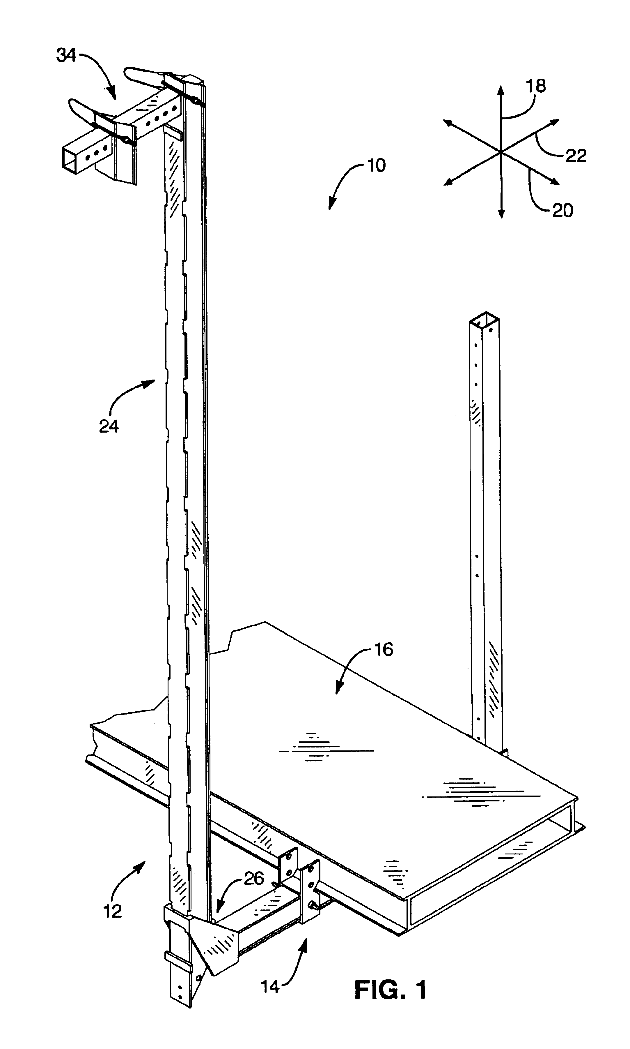
[0037]Referring to FIG. 1, an apparatus 10 may include one or more scaffold supports 12 providing one or more bases 14 for supporting a work surface 16. The work surface 16 (or deck 16) may be embodied as a plank or planks made of wood, aluminum, ferrous alloy, or the like. A ...


PUM


Abstract

A scaffold support system having an adjustable-width hanger. A vertical leg may support a foot upon which rests a deck, providing a working surface during building construction or modification. A lateral beam rests on a support structure forming part of the wall of a building with the vertical leg securing to the lateral beam at a plurality of points. A stop secured to the lateral beam to capture a support structure between itself and the vertical leg. The stop may be adjustable along the lateral beam to accommodate support structures of varying widths. An operator may insert the hanger from inside a building and pass the coupler through a gap between a frieze block and a top plate, presenting the coupler for securement to the vertical leg. A catch may slide along the foot into and out of engagement with an edge of the deck to prevent rotation of the deck.

Description

BACKGROUND[0001]1. The Field of the Invention[0002]This invention relates to supporting structures for use during construction, and more particularly to novel systems and methods for supporting decking for workmen above ground level in residential or other construction projects similar in nature.[0003]2. The Background Art[0004]Scaffolding has long been of both utility and concern in construction. In many states as well as in federal regulations, detailed specifications-of requirements apply to “riggers” and their craft. Scaffolding may be thought of as decking for supporting materiel, workmen, tools, and the like, above or below a common surface.[0005]For example, a workman may stand on the ground while laying brick, working on certain woodwork, while wiring, and so forth. In construction of large, multi-storied buildings, special decking may be laid specifically for use during construction. Many feet above ground level, scaffolding built from the ground up becomes impractical. How...

Claims


Application Information

Patent Timeline
Patent Type & Authority Patents(United States)
IPC IPC(8): E04G5/00E04G5/04E04G3/28E04G3/22
CPCE04G3/22E04G5/048E04G5/04E04G3/28E04G5/041
Inventor RILEY, D. PAUL
Owner JDPR INVESTMENTS LLC
Why Eureka
Try Eureka