
VTOL personal aircraft

Inactive Publication Date: 2005-05-03
MILDE KARL F JR
View PDF48 Cites 205 Cited by
  • Summary
  • Abstract
  • Description
  • Claims
  • Application Information

AI Technical Summary

Benefits of technology

[0012]A principal object of the present invention is to provide an aircraft configuration which is potentially less costly to construct, and substantially safer and less expensive to fly, than either the Sikorsky helicopter or the Moller SkyCar.
[0013]A more particular object of the present invention is to provide a thruster for an aircraft in the form of a ducted fan unit which is more efficient, and provides greater lift per horsepower, than thrusters heretofore known.
[0014]A still further object of the present invention is to provide an aircraft having an efficient fixed wing for forward, horizontal flight, with integrated, highly efficient thrusters for forward propulsion as well as vertical take-off and landing.

Problems solved by technology

As early as 1926, no less a visionary and hard-nosed businessman than Henry Ford himself attempted to develop the “Ford flying flivver” but the technology of the day was simply not up to the task.
Principally due to its control system, which includes a complex mechanism for continuously adjusting the pitch of individual rotating blades, the helicopter is extremely expensive to construct and to maintain.
It is also not possible to provide redundancy so that failure of any drive element can result in a crash.
Further, the helicopter is notoriously difficult to fly.
Another disadvantage is its relatively high rate of fuel consumption, both while hovering and in forward, horizontal flight, as compared to a helicopter.
Its major problem is that, in replacing a helicopter's “rotary wings” with small ducted fans, it requires approximately four times the horsepower to maintain it aloft, in the hover mode.

Method used


Image

  • VTOL personal aircraft
  • VTOL personal aircraft
  • VTOL personal aircraft

Examples


first embodiment

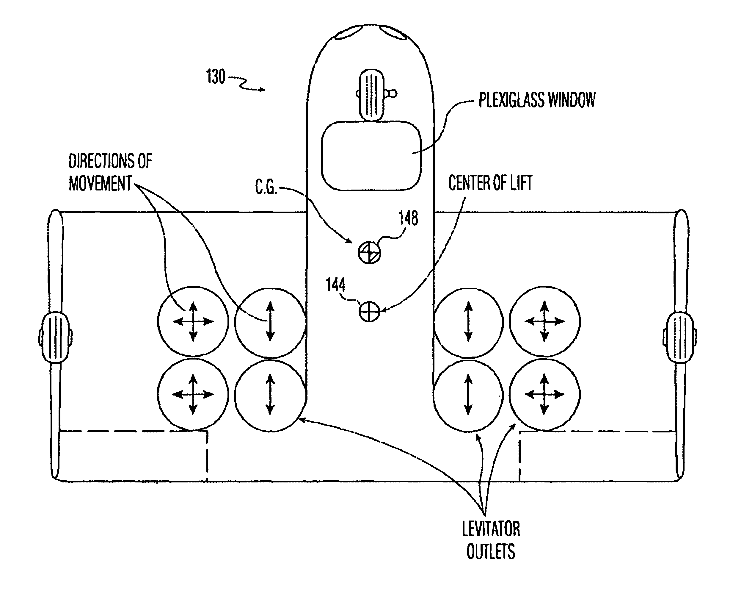
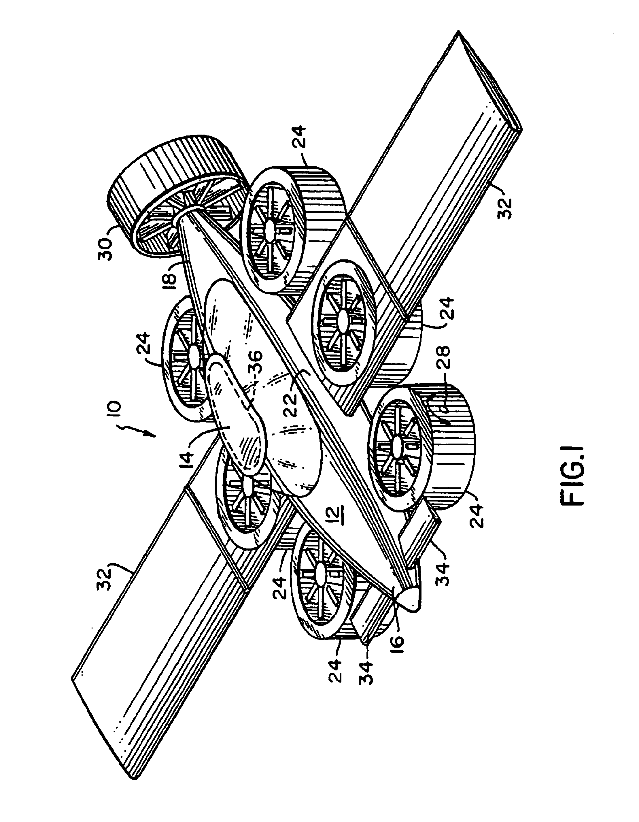
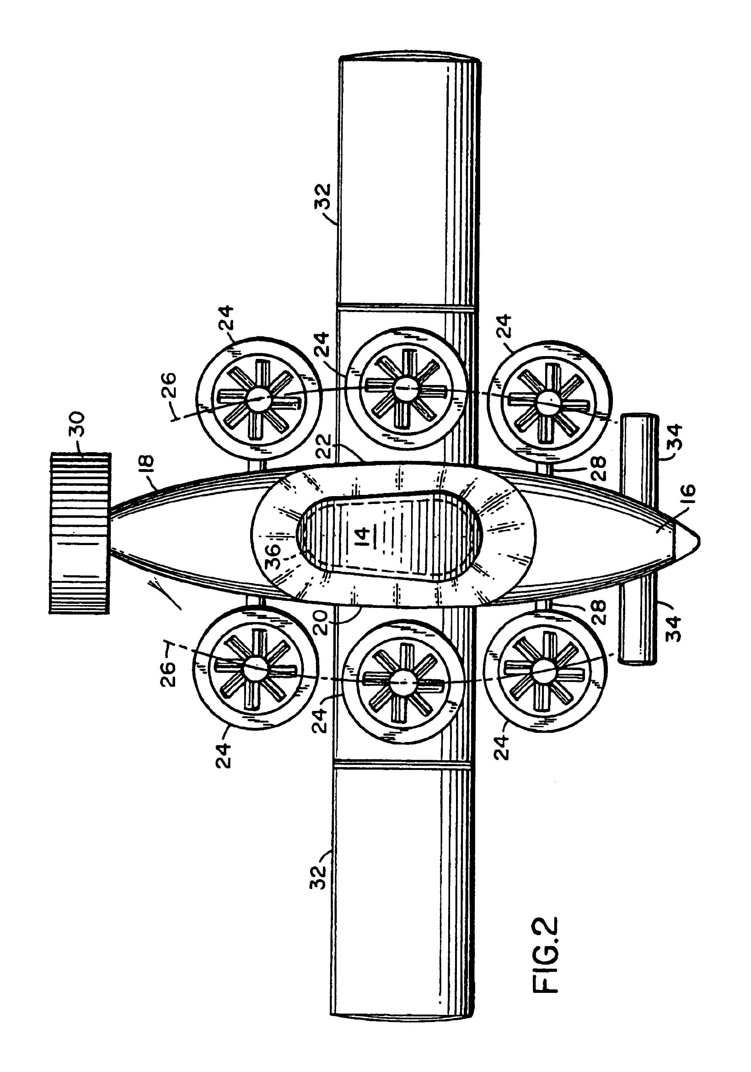
[0157]First and Second Preferred Embodiments of the PAC: In the invention, shown in FIGS. 1-4, the personal aircraft (PAC) 10 comprises a fuselage 12, forming a passenger compartment, having a top 14, a front 16, a rear 18 and two sides 20 and 22, respectively. Attached to each side of the compartment are at least two, and in this case three, “thrusters”24, preferably ducted fan units. These fan units may, for example, be the type employed by Moeller International Corp. in the aforementioned Skycar. Other ducted fan units are disclosed in the aforementioned U.S. Pat. No. 6,179,247.

[0158]Because of the redundancy of thrusters, the loss of power in one thruster on each side would not result in a catastrophic failure of lift. By increasing the thrust of the remaining thrusters on the side where the failure occurred, the craft will remain under control and can be lowered safely to the ground.

[0159]As shown in FIG. 2, the central, rotational axes of the thrusters 24 are arranged along a ...

second embodiment

[0167]In the invention, shown in FIGS. 5-8, the personal aircraft (PAC) 40 comprises a passenger compartment or fuselage 42 in the shape of a “lifting body” having a front side 44, rear side 46 and two lateral sides 48 and 50. Built into the front side 44 are three thrusters 52 in the form of ducted fan units. Also, built into the rear side 46 are three thrusters 54, also in the form of ducted fan units. These thrusters are independently powered, for reasons of redundancy, and are capable of providing vertical lift. These thrusters also provide lateral thrust to the aircraft when the craft is tilted, either forward or backward, or when the thrust is deflected laterally by one or more deflectors (not shown).

[0168]As shown in FIG. 6 in top view and in FIG. 8 in cross sectional view, the ducted fan units 52 and 54 comprise a tapered opening 56 and 58, respectively, and a circular tube 60 and 62, respectively, in which the air is accelerated by one or more impellers driven by one or mor...


PUM


Abstract

A personal aircraft (PAC) capable of vertical take-off and landing (VTOL) comprises a fixed wing and a fuselage with a passenger compartment having a front, a rear and two sides, and a plurality of independently powered thrusters, preferably integrated into the wing, on each side of the fuselage. The aircraft has a lift to drag ratio equal to or greater than 2. The thrusters, which are ducted fan units capable of providing a vertically upward force to the aircraft, are provided with such redundancy that the aircraft can hover with at one thruster inoperative on each side of the fuselage. At least one thruster on each side of the fuselage preferably comprises a “levitator” which creates lift from the airfoil-like air inlet as well as from the acceleration of air from inlet to outlet.

Description

CROSS-REFERENCE TO RELATED APPLICATION[0001]This application is a continuation-in part of application Ser. No. 10 / 114,754 filed Apr. 2, 2002, which, in turn is a continuation-in-part of application Ser. No. 09 / 968,934 filed Oct. 2, 2001. This application also claims subject matter disclosed in the provisional patent application Ser. No. 60 / 354,808, filed Feb. 6, 2002.BACKGROUND OF THE INVENTION[0002]There is one major industry which has been predicted and anticipated for many years, but has yet to materialize: the production and sale of small, affordable, vertical take-off and landing (VTOL) aircraft, called a “Personal Aircraft” or “PAC” for short. The present invention relates to the fundamental characteristics of this craft.[0003]Since the appearance of the ubiquitous automobile, people have simply assumed that an inexpensive, easy to fly, VTOL aircraft would someday be in our future. As early as 1926, no less a visionary and hard-nosed businessman than Henry Ford himself attempt...

Claims


Application Information

Patent Timeline
IPC IPC(8): B64C27/20B64C27/00B64C29/00B64C3/00B64C3/56
CPCB64C3/56B64C29/0025B64C27/20Y02T50/145Y02T50/10
Inventor WAGNER, JOSEPHPRUSZENSKI, JR., ANTHONYMILDE, JR., KARL F.
Owner MILDE KARL F JR
Learn More