An ocean wave energy extraction system and components thereof

a technology of energy extraction system and components, applied in the field of ocean wave energy extraction system, can solve the problems of affecting the energy conversion efficiency of paddle systems, the majority of wave powered generation systems proposed to date have not been physically practical and/or economically viable, and the cost of the system is high

Inactive Publication Date: 2003-09-23
ENERGETECH AUSTRALIA
View PDF11 Cites 32 Cited by
  • Summary
  • Abstract
  • Description
  • Claims
  • Application Information

AI Technical Summary

Benefits of technology

In another form, that may be less costly to construct, the structure comprises an air compression chamber wherein the rear wall portion maybe formed in part by the existing coast line and the bay is defined simply by two possibly relatively short arms of part parabolic curvature extending from the chamber walls. Generally, any compromise on the length of the parabolically curved arms is compensated for by extending the plan area of the air compression chamber that circumscribes the energy harnessing region.
Preferably, the bay is further bounded at its base by a generally planar sea bed that is of constant depth along a direction generally perpendicular to the axis of symmetry of the parabola. The depth and inclination (if any) of the sea bed can vary according to local strata and wave conditions, as well as the manner in which the amplified waves are to be harnessed for energy extraction. The general aim will be to optimise local conditions to maximise the wave magnification, ideally without the waves breaking prior to entering the harnessing region. For example, in one preferred form, the sea bed may slope upwardly toward the harnessing region to assist in further forcing the water upwardly at that location.
whereby the approximately symmetrical shape of the blades and their orientation in relation to the hub facilitates unidirectional rotation of the rotor in response to reversing axial fluid flows therethrough.

Problems solved by technology

Whist significant technological advances have been made in the conversion of energy from some of these alternative areas such as wind and solar, the majority of wave powered generation systems proposed to date have not been physically practical and / or economically viable.
However, all of the systems proposed so far have had their limitations.
However, these floating paddle systems generally have a low energy conversion efficiency and are unable to withstand adverse weather conditions.
This means either that such systems are limited to coastal locations having only moderate and predictable wave patterns, or that the systems must be removed to a suitable shelter when storms are expected.
Again, the main deficiencies with these latter wave driven air turbine systems, is the restricted overall achievable energy efficiencies.
This is due primarily to the limitations firstly in the means of focusing the wave energy to maximise the wave displacement amplitude, and secondly in the operating efficiencies inherent in the turbine design.
Once again these types of systems have been limited so far in respect of the maximum achievable wave amplification for a given level of capital expenditure.
In the second case most prior art turbines are designed for constant velocity rotation in response to fluid flow in one direction only, and as such are unable to operate continuously in response to the reversing fluid flow conditions present in wave powered applications of the kind discussed above.
However, a number of specially configured unidirectional turbines have been designed for these reversing flow conditions, the most commonly used devices being based on what is known as the "Wells" turbine.
However, these early turbines were known to suffer from stalling, often resulting in the shut down of the wave energy harnessing plant.
This stalling occurs due to the fact that such a turbine needs to be designed around anticipated levels of air flow, whereas the size of the waves entering the turbine chamber cannot be controlled for all occasions.
While this modified system solves the stalling problem, it does so at a penalty to the overall efficiency.
This is because it sacrifices the first set of blades by allowing them to correspondingly stall and shut down, the second set of blades then continuing operation at a reduced pace and efficiency.
It will therefore be-appreciated that most prior art turbines suited to this type of application are often quite complex in design and usually have severe limitations in relation to operating conditions and / or efficiencies.

Method used


Image

  • An ocean wave energy extraction system and components thereof
  • An ocean wave energy extraction system and components thereof
  • An ocean wave energy extraction system and components thereof

Examples


first embodiment

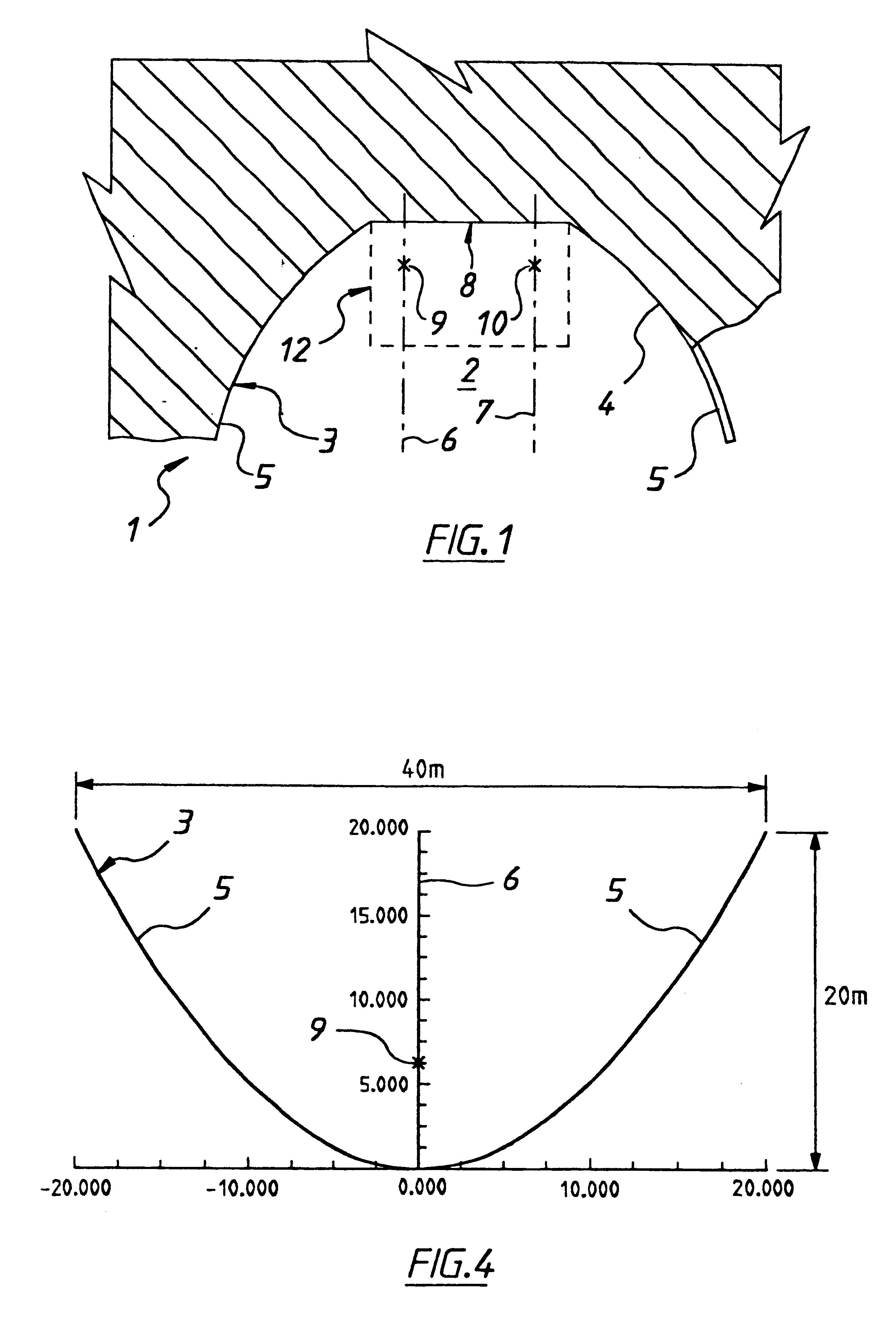
Referring firstly to FIG. 1, there is shown a first embodiment wave focusing structure in accordance with the first aspect of the invention denoted generally by reference numeral 1.

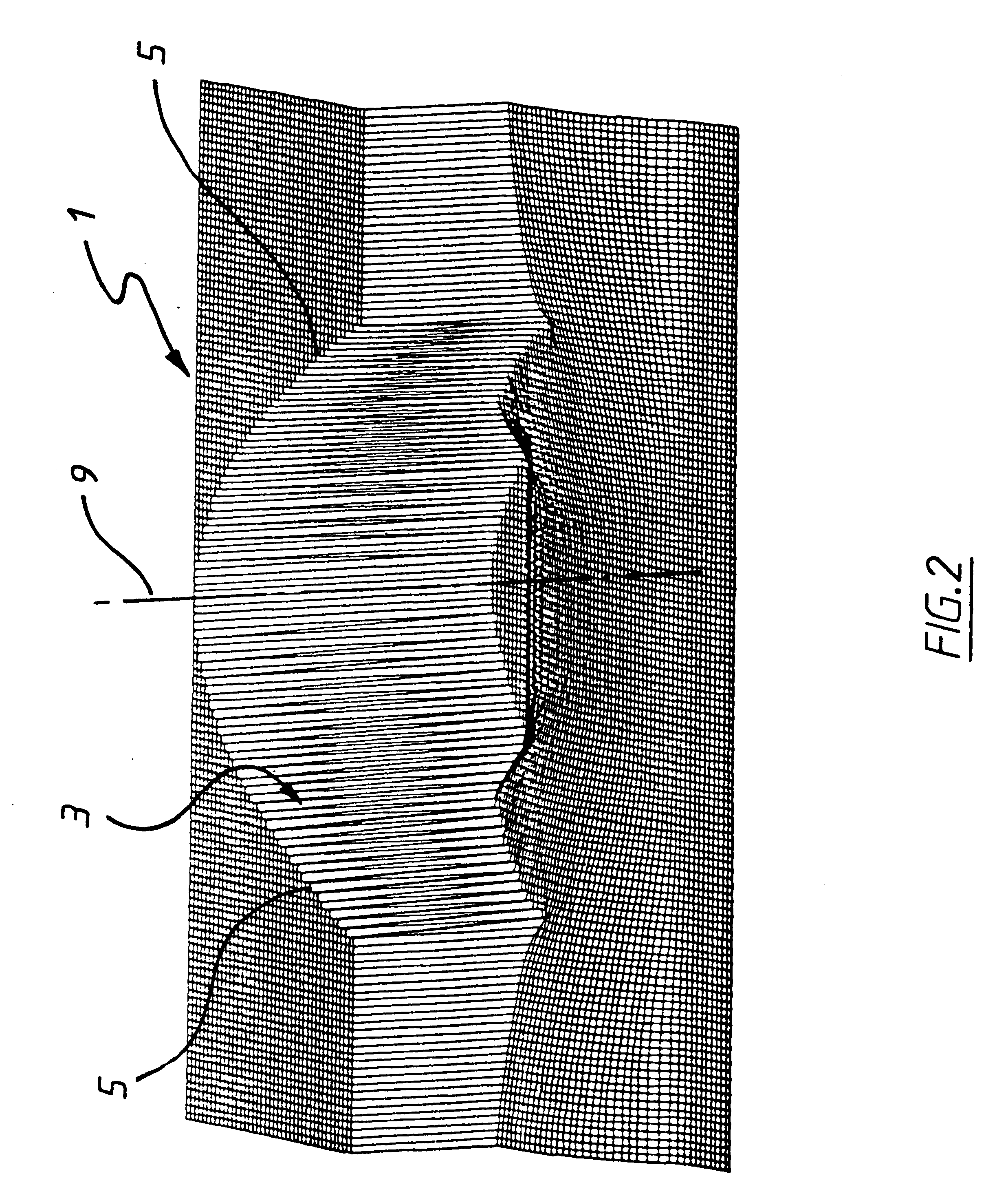
The structure 1 comprises an open sided bay 2 bounded by a generally upright sea wall 3. The wall 3 is concavely curved at its inner periphery 4 to define in plan two converging arms 5 of generally part parabolic curvature, wherein the respective axes of symmetry 6 and 7 of the paraboli from which the arms are derived are parallel. The arms 5 are joined adjacent their converging ends to form a shared apex 8. The wall 3 is oriented to admit an advancing wave front that is propagating in a direction generally parallel to the axes of symmetry 6 and 7.

FIG. 5 shows another variation on the structure illustrated in FIG. 1 which may be employed when it is too costly or not possible to construct the wall of the bay as either part of the surrounding coastline or having long parabolic arms extending out into the ba...

second embodiment

In use, the wave focusing structure is orientated as described, such that the plane wave advances toward the parabolic or part parabolic wall 3 in a direction generally parallel to the axis (or axes) of symmetry 6 and 7. On impact with the parabolic sections 5 of the wall 3, the wave is reflected to converge toward the corresponding focus 9 or foci 9 and 10 of each respective parabola. When the wall defines part of a single parabola as in the preferred second embodiment shown in FIGS. 2, 3 and 4, the wave converges toward the single focus 9 as a circular or polar wave. At this point, the displacement amplitude of the wave will have been significantly magnified, making it the perfect plan location at which to position suitable means for converting that sea water displacement to another more useable energy form. This is defined as the energy harnessing region shown generally at 12 which in FIG. 5 corresponds in location with air compression chamber 11. It will be appreciated that the ...


PUM


Abstract

The invention relates to wave powered energy extraction systems and the components thereof, in which the oscillating ocean wave motion is used to displace a volume of air to drive a wind operated turbine connected to an electrical generator. The various aspects of the invention include: a parabolic or part parabolic wave focusing device (1); an air compression chamber arrangement particularly suited for use with the wave focusing device; a wind turbine operable to rotate unidirectionally under periodically reversing air flow conditions of the kind contemplated above.

Description

The present invention relates in general to systems for harnessing and converting the energy from ocean waves to more useable energy forms such as electric power.More particularly, the invention relates to wave powered energy extraction systems and the components thereof, in which the oscillating ocean wave motion is used to displace a volume of air to drive a wind operated turbine connected to an electrical generator. In the preferred form of the invention, the waves are directed into a specially configured air compression chamber, in the outlet of which is arranged a suitably operable wind turbine.To this end the various aspects of the invention include: a novel wave focusing device; an air compression chamber arrangement particularly suited for use with the novel wave focusing device; and an independently novel wind turbine operable to rotate unidirectionally under periodically reversing air flow conditions of the kind contemplated above.It will be appreciated that whilst the var...

Claims


Application Information

Patent Timeline
Patent Type & Authority Patents(United States)
IPC IPC(8): E02B9/08E02B9/00F03B13/14F03B13/00F03B13/24
CPCE02B9/08F03B13/142Y02E10/32Y02E10/38Y02E10/30
Inventor DENNISS, TOM
Owner ENERGETECH AUSTRALIA
Why Eureka
Try Eureka