Rear bicycle suspension

a bicycle and suspension technology, applied in the field of rear bicycle suspensions, can solve the problems of poor pedaling performance, undue friction along the seals, guide bushings and control shafts, and the tendency of great suspension movement to give way, and achieve the effect of minimal side loading

Inactive Publication Date: 2005-05-03
CARROLL RYAN MICHAEL
View PDF5 Cites 40 Cited by
  • Summary
  • Abstract
  • Description
  • Claims
  • Application Information

AI Technical Summary

Benefits of technology

[0024]FIG. 7 is an elevation view of the progressive link system showing a minimum in side loading of the shock absorbing member upon compression.

Problems solved by technology

A problem exists in that a great suspension movement usually gives way to poor pedaling performance and vice versa.
The change in mounting angle produces this side loading of the shock absorbing member with the horizontal force, causing undue friction along the seals, guide bushings and control shaft.
The added friction resists allowing the swing arm to rotate upwardly and reduces the smoothness and control of the rear wheel in response to an irregularity in the roadway.
All of these factors contribute to decrease service of life of the shock-absorbing member.

Method used


Image

  • Rear bicycle suspension
  • Rear bicycle suspension
  • Rear bicycle suspension

Examples


Embodiment Construction

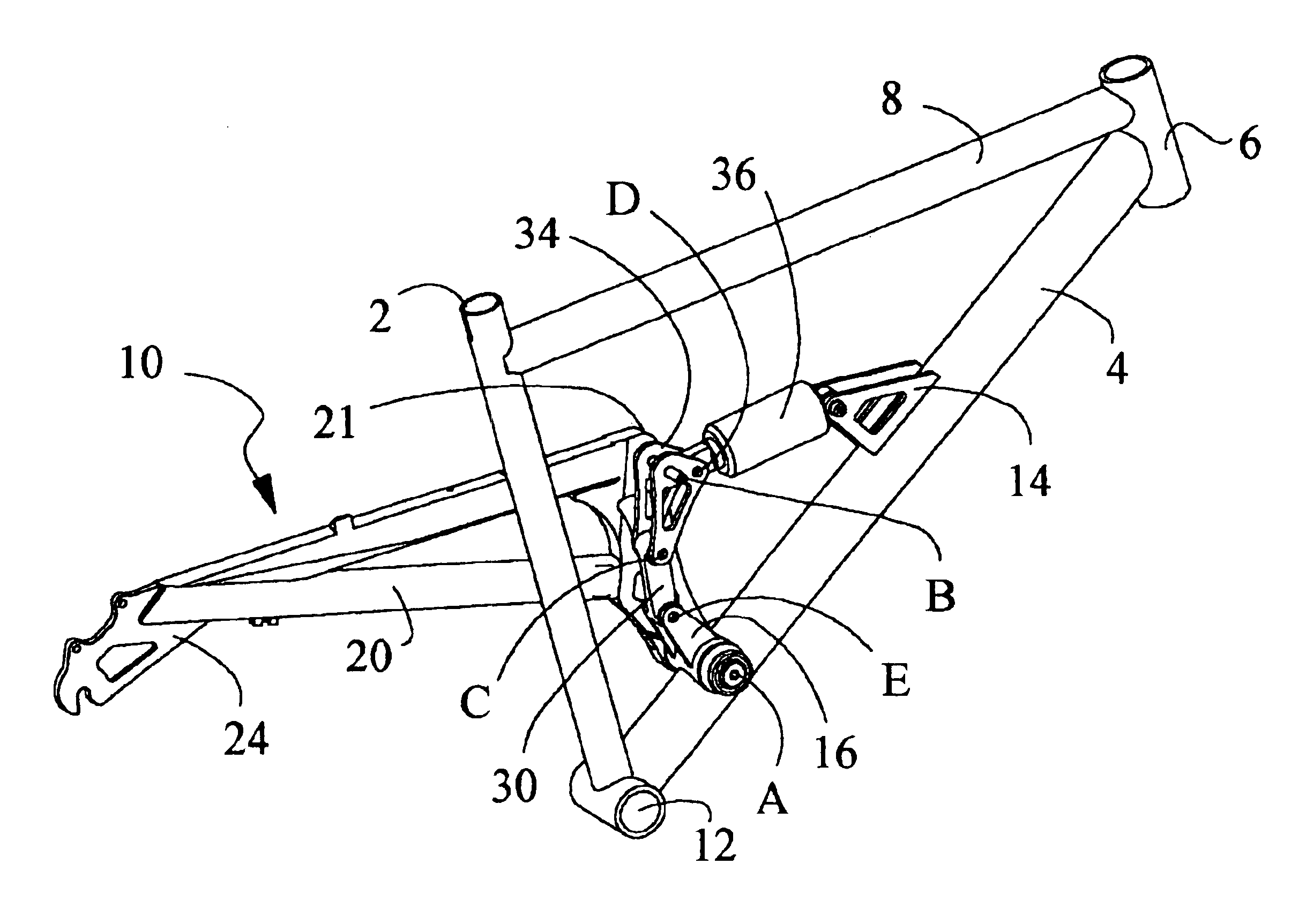
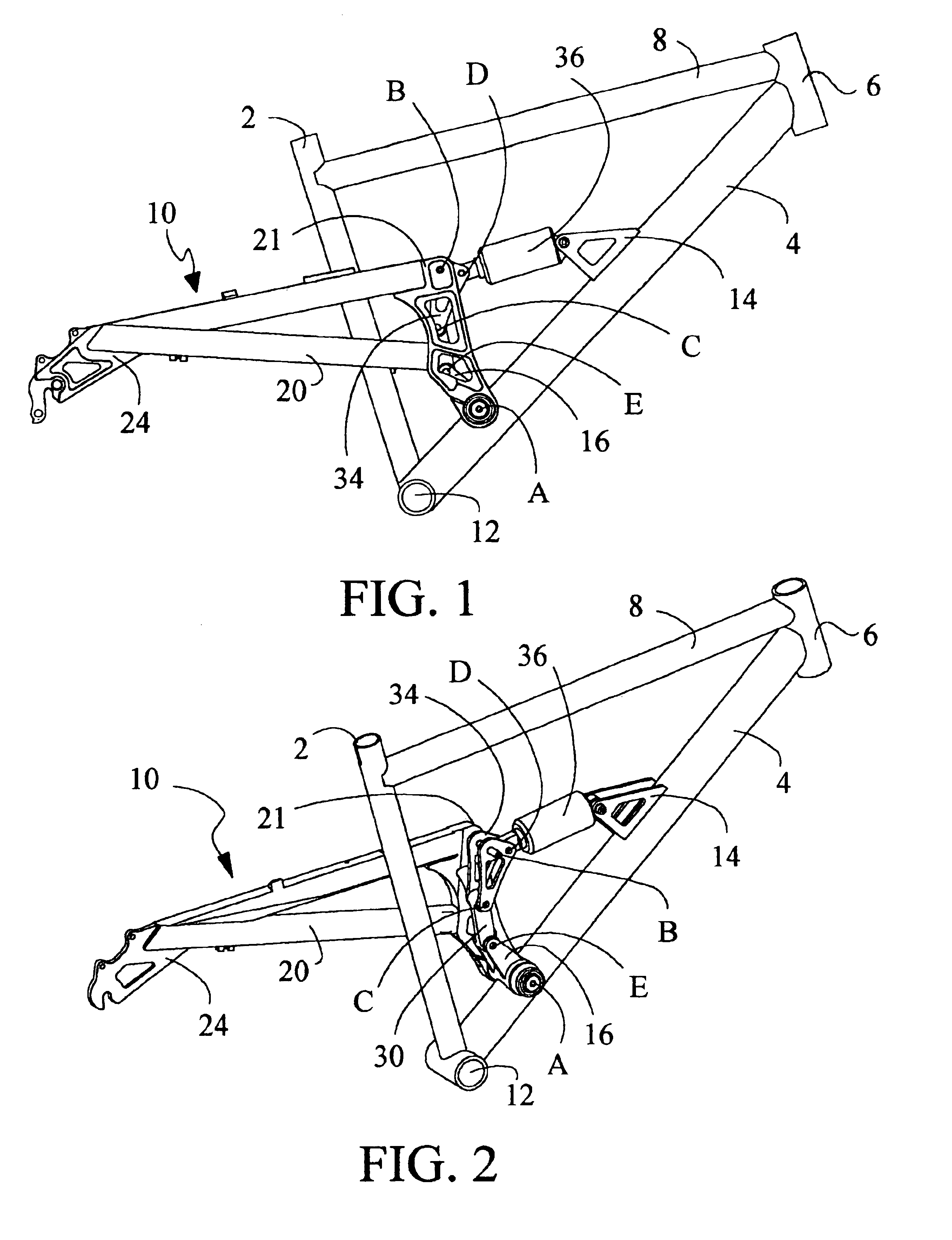
[0025]Referring now to the drawing figures wherein like numerals represent like features there is shown in FIGS. 1 and 2 an embodiment of my suspension system when used in conjunction with a single pivot system. This system utilizes an optimized single pivot suspension location that works with my progressive link assembly, described below, to optimize the rear shock spring tuning. The single pivot system works because the travel is limited to four inches and the swing arms only follow a rear arching path. If the travel were more than this an arching forward problem encountered with many prior art suspensions would arise.

[0026]In FIGS. 1 and 2, a bicycle frame is shown which incorporates the rear suspension 10, according to the present invention, in the single pivot configuration. The rear suspension 10 of the present invention can also be used on other types of bicycles, as well as motorcycles, but the preferred embodiment is described herein as used on a mountain bike. The mountain...


PUM


Abstract

A rear bicycle suspension has a main frame including a seat riser tube, a down tube, head tube, and a bottom bracket housing having left and right sides, a guide arm and a shock mount attached to the main frame, a pair of swing arm assemblies each one in pivotal attachment on either side of the main frame at a first pivot point and to a bell crank at a second pivot point, the swing arms in rearward extension form the first and second pivot points to at least one rear swing arm attachment point, and further including a lever arm connected between the first and the second pivot points, a guide arm having first and second ends wherein the first end in pivotal attachment to the guide arm bracket at a fifth pivot point and the second end extends upward and rearward from the fifth pivot point, wherein the bell crank is pivotally connected between the lever arms at the second pivot point and to the guide arm at a third pivot point, a shock absorbing member in pivotal attachment at one end to the shock mount and at another end at a fourth pivot point to the bell crank.

Description

CROSS REFERENCE TO RELATED APPLICATIONS[0001]Pursuant to 35 U.S.C. §119(e)(1) this Application claims the benefit of the 35 U.S.C. §111(b) Provisional Application Ser. No. 60 / 408,712, filed Sep. 6, 2002.BACKGROUND OF THE INVENTION[0002]1. Field of the Invention[0003]This invention relates to rear bicycle suspensions. More particularly, it relates to rear shock absorbing suspensions.[0004]2. Description of the Related Art[0005]Rear shock absorbing suspensions for bicycles, such as a mountain bike, are well known in the art. Most of the prior art designs are configured with a goal of optimizing pedal force neutralization or providing great suspension movement. However, to provide a good all-around freerider bike, a more sturdy and durable the bike is needed. A problem exists in that a great suspension movement usually gives way to poor pedaling performance and vice versa.[0006]To provide a durable suspension it is also desirable to maximize the service life of the shock absorbing memb...

Claims


Application Information

Patent Timeline
Patent Type & Authority Patents(United States)
IPC IPC(8): B62K25/28B62K25/04
CPCB62K25/28
Inventor CARROLL, RYAN MICHAEL
Owner CARROLL RYAN MICHAEL
Why Eureka
Try Eureka