Shock-mounted imaging module with integrated window for resisting back reflections in an imaging reader

Inactive Publication Date: 2012-03-01
SYMBOL TECH INC
View PDF5 Cites 20 Cited by
  • Summary
  • Abstract
  • Description
  • Claims
  • Application Information

AI Technical Summary

Benefits of technology

[0012]Hence, by positioning the window substantially perpendicular to the imaging axis and as close as possible to the imaging lens assembly and to the illuminating light assembly, any back reflections are minimized, because any such back reflections do not enter the field of view of the imager. A relatively large spacing between the window and the imaging module is no longer needed to prevent scratching, cracking and breakage of the window when the reader is subjected to shock forces. The window is thus protected from such damage, and such back reflections are minimized.
[0013]Another feature of the present invention is that the imaging module with its integrated window can be easily installed in original equipment manufacturer (OEM) product applications. Product integrators of the imaging module do not need to be concerned with correctly locating the exit window in the final product, since the window is already provided with the imaging module. The imaging module with its

Problems solved by technology

Although the known imaging reader is generally satisfactory for its intended purpose, one problem associated with spacing the housing window away from the imaging module relates to back reflections of the illumination light emitted by the illuminating light source, or from any other interior light source, off the window and inwardly back toward the imaging lens assembly.
These back reflections into the field of view of the imager may create hot spots or stray light in the captured target image.
Any dust and like contaminants that are deposited on the window, and/or any imperfections in the window itself, are substantially highlighted by the illumination light, thereby degradin

Method used


Image

  • Shock-mounted imaging module with integrated window for resisting back reflections in an imaging reader
  • Shock-mounted imaging module with integrated window for resisting back reflections in an imaging reader
  • Shock-mounted imaging module with integrated window for resisting back reflections in an imaging reader

Examples


Embodiment Construction

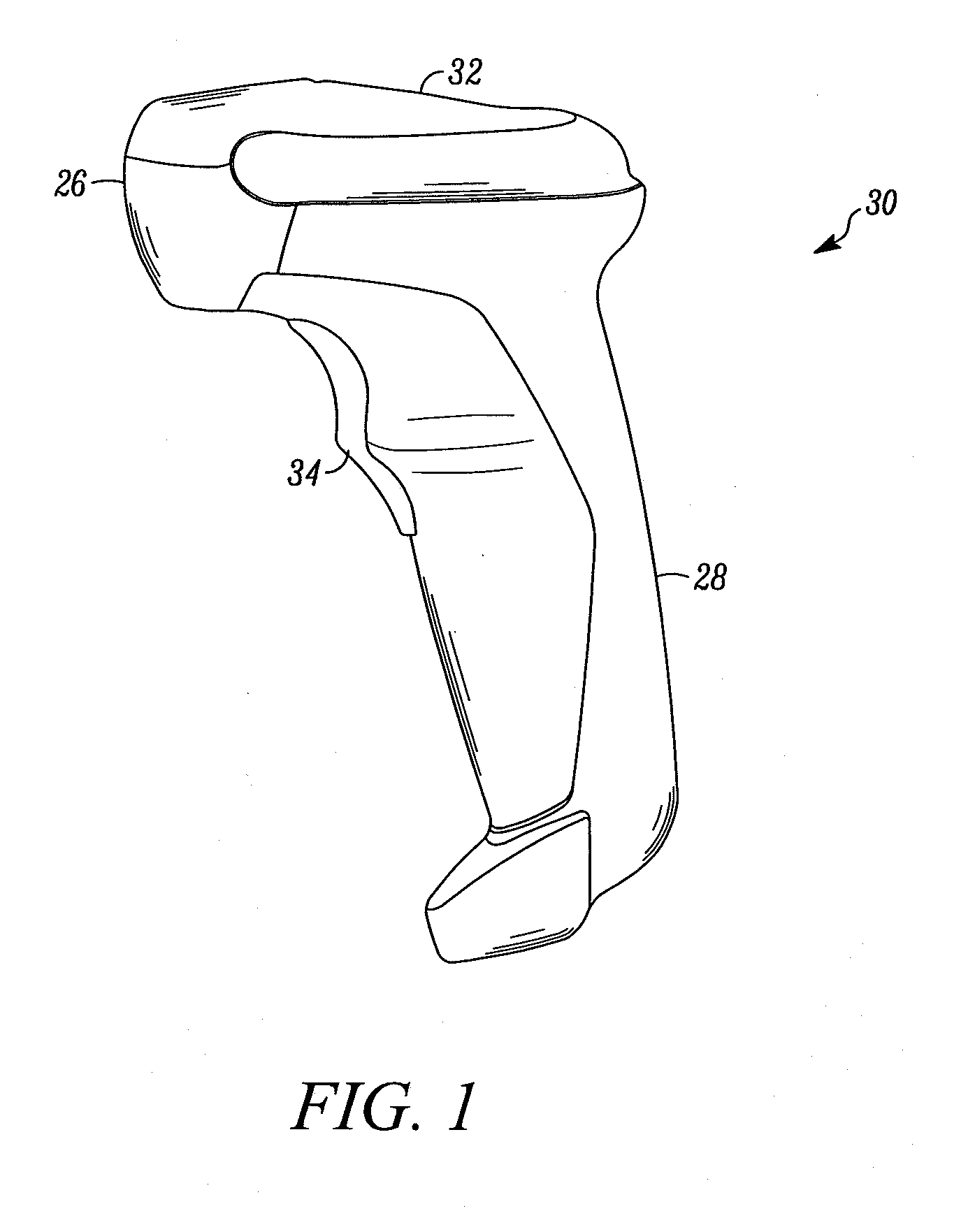
[0023]Reference numeral 30 in FIG. 1 generally identifies an ergonomic imaging reader configured as a gun-shaped housing having an upper housing part 32 and a lower housing part 28 that includes a handle tilted rearwardly away from the upper housing part 32 at an angle of inclination, for example, fifteen degrees, relative to the vertical. A window 40, as described in detail below, is located adjacent the front or nose 26 of the upper housing part 32. The imaging reader 30 is held in an operator's hand and used in a handheld mode in which a trigger 34 is manually depressed to initiate imaging of a target or symbol, especially one-dimensional symbols, to be read in a range of working distances relative to the window. Housings of other configurations can also be employed and operated in other modes, such as a hands-free mode of operation, by being supported on a countertop or like support surface.

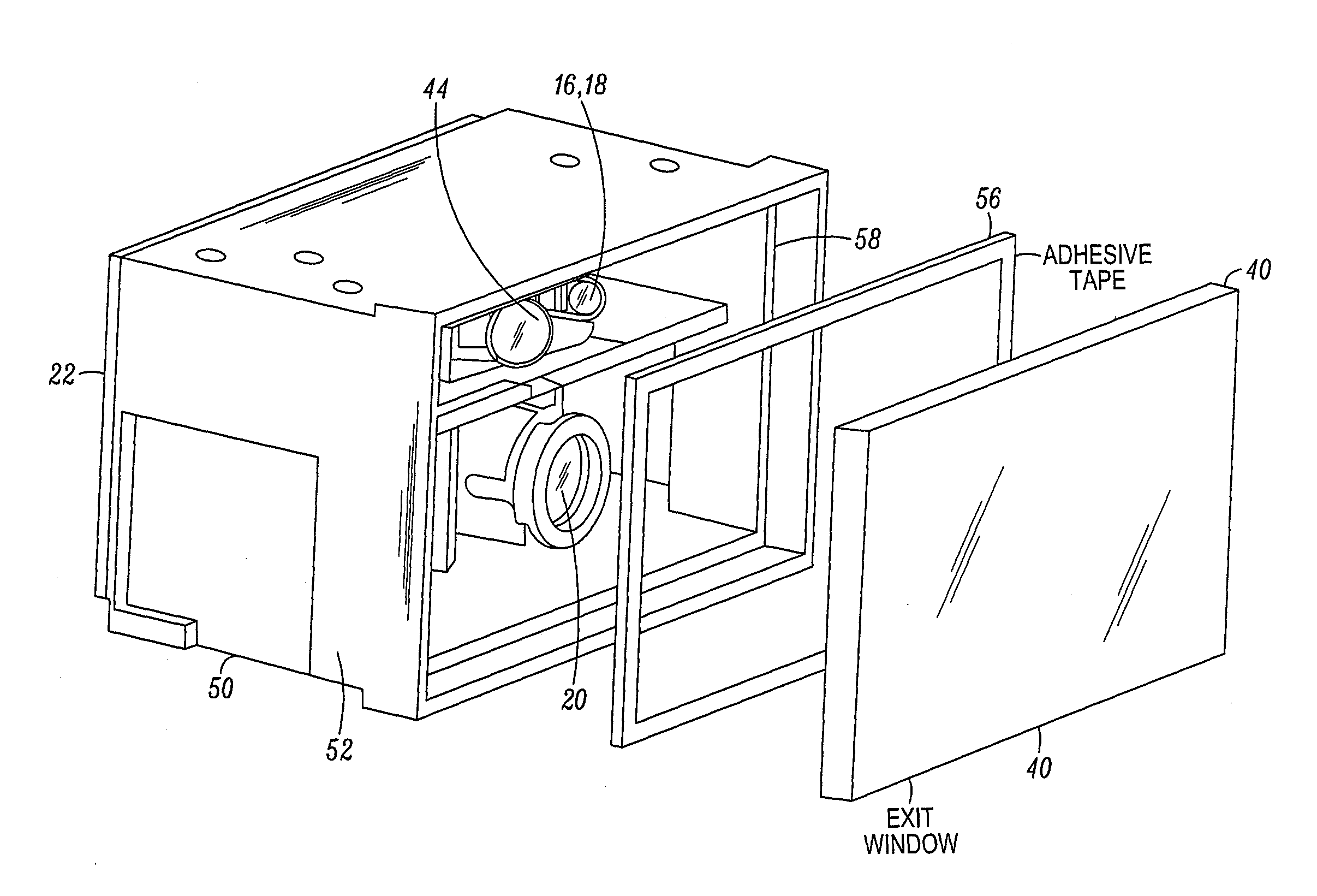
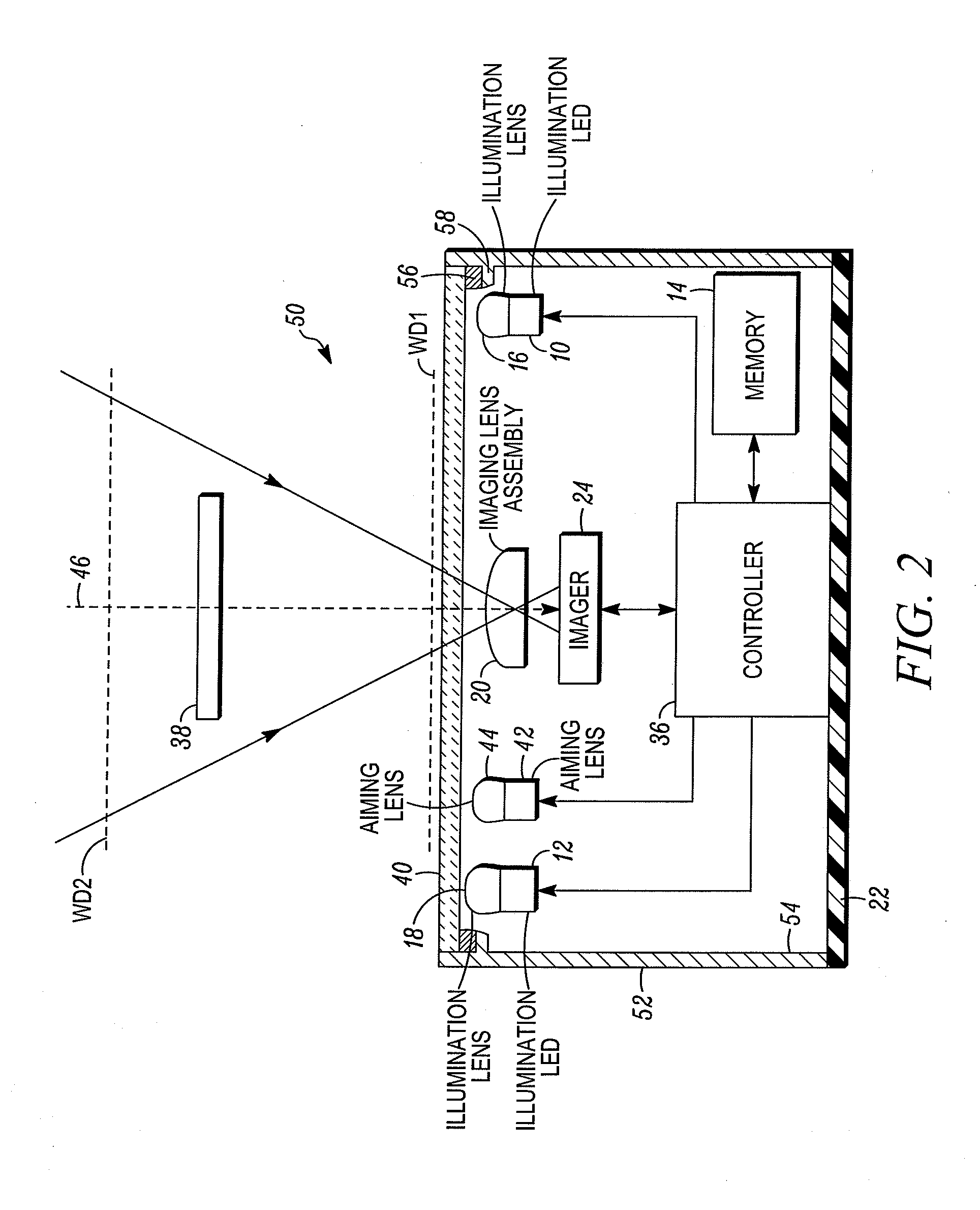
[0024]As schematically shown in isolation in FIG. 2, an imaging system or module 50 is mo...


PUM


Abstract

An imaging module for an imaging reader for electro-optically reading a target by image capture, includes a chassis bounding an optical compartment, an illuminating light assembly in the compartment for illuminating the target with illumination light for return from the target, an image capture assembly in the compartment for capturing return light from the target over a field of view, and a light-transmissive window for the reader. The window is supported by, and integrated with, the chassis for joint movement therewith. The window is preferably positioned in a close confronting relationship with the illuminating light assembly to resist back reflections of the illumination light from the window from entering the field of view of the image capture assembly. The integrated imaging module is shock mounted in the reader to damp shock forces.

Description

DESCRIPTION OF THE RELATED ART[0001]Solid-state imaging systems or imaging readers have been used, in both handheld and / or hands-free modes of operation, to electro-optically read targets to be decoded, such as one-dimensional bar code symbols, particularly of the Universal Product Code (UPC) symbology having a row of bars and spaces spaced apart along a scan direction, as well as two-dimensional symbols, such as the Code 49 symbology having a plurality of vertically stacked rows of bar and space patterns in a single symbol, as described in U.S. Pat. No. 4,794,239, and even non-symbol targets to be imaged, such as documents.[0002]The known imaging reader includes a housing either held by an operator and / or supported on a support surface, a window supported by the housing and aimed at the target during reading, and an imaging engine or module supported by the housing and spaced away from the window. The imaging module has a chassis bounding an optical compartment in which are accommo...

Claims


Application Information

Patent Timeline
IPC IPC(8): H01L31/0232G06K7/14
CPCG06K7/1098G06K7/10881
Inventor VINOGRADOV, IGORFRATIANNI, EDMOND L.
Owner SYMBOL TECH INC
Why Eureka
Try Eureka