Unidirectional dynamic microphone

a dynamic microphone and microphone technology, applied in the direction of piezoelectric/electrostrictive transducers, mouthpiece/microphone attachments, microphone structural associations, etc., can solve the problems of high labor intensity, low productivity, and above-described conventional examples, so as to reduce the number of components, reduce the noise of handling, and reduce the number of defective parts in the final assembly

Inactive Publication Date: 2005-10-13
AUDIO-TECHNICA
View PDF6 Cites 19 Cited by
  • Summary
  • Abstract
  • Description
  • Claims
  • Application Information

AI Technical Summary

Benefits of technology

[0011] According to this configuration, since the air chamber is provided in the cavity sleeve supported in the grip housing via the shock mount members, even if an external force caused by tapping or rubbing is applied to the grip housing, the volume of the air chamber does not change. Therefore, handling noise is reduced. Also, since the performance can be measured at a stage before the cavity sleeve is assembled into the grip housing, namely, in the state of subassembly, defectives in final assembly can be reduced.
[0012] As a preferable mode, a rear end part of the microphone unit is fitted on one end side of the cavity sleeve, and on the other end side of the cavity sleeve is airtightly installed a connector support cover for the output connector; and the connector support cover is formed by a rubber elastic body to be also used as one of the shock mount members. According to this configuration, since the connector support cover can be used as the shock mount member, the number of components can be reduced.
[0013] Also, it is preferable that the connector support cover should be formed with a pin insertion hole, and a terminal pin of the output connector should be airtightly inserted through the pin insertion hole. According to this configuration, since a sealing compound such as silicon sealant is not needed, the assembling / disassembling work can be performed easily.

Problems solved by technology

However, the above-described conventional example has problems as described below.
Next, regarding the workability, the sealing compound is difficult to pour, and also waiting time is required before curing, so that the productivity is low.
Also, when the output connector 30 is damaged and replaced, for example, by a drop shock and the like, the sealing compound 15 must be scraped off, which requires much time and labor.

Method used


Image

  • Unidirectional dynamic microphone
  • Unidirectional dynamic microphone
  • Unidirectional dynamic microphone

Examples


Embodiment Construction

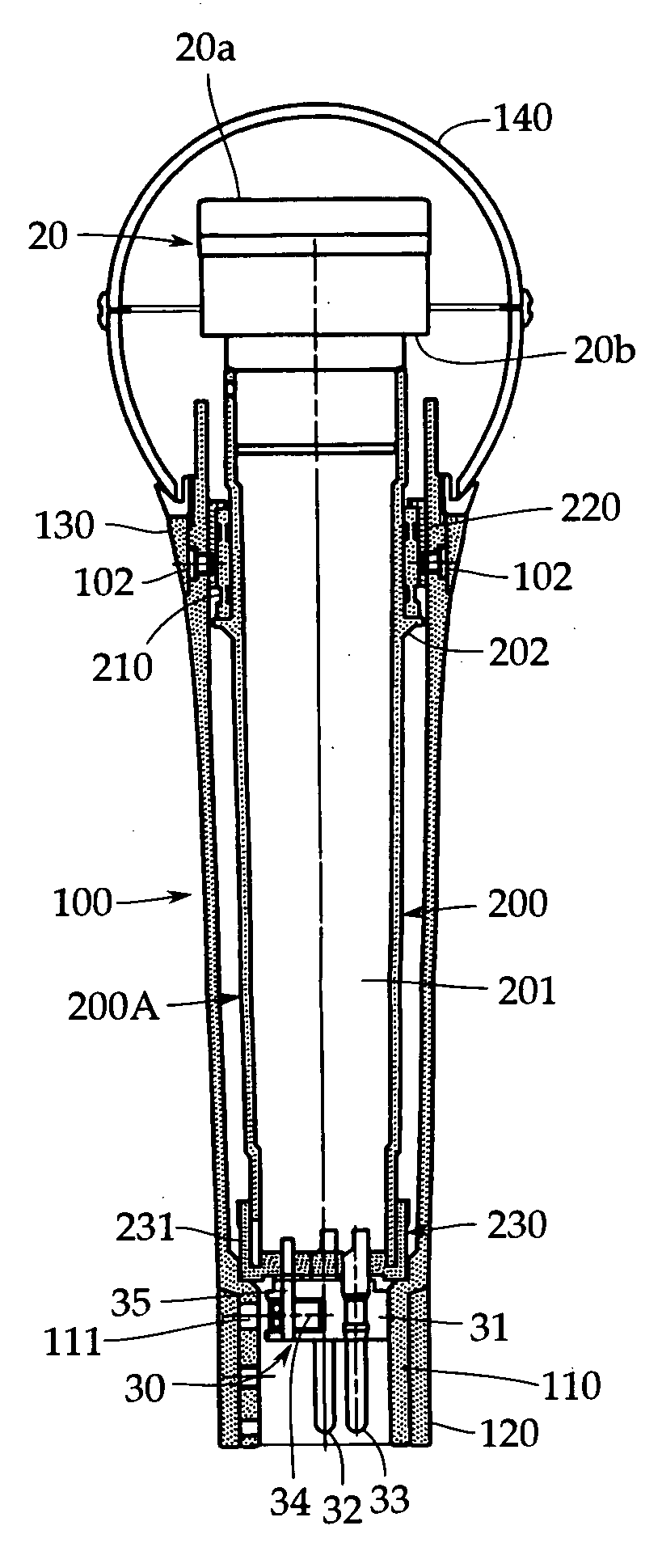
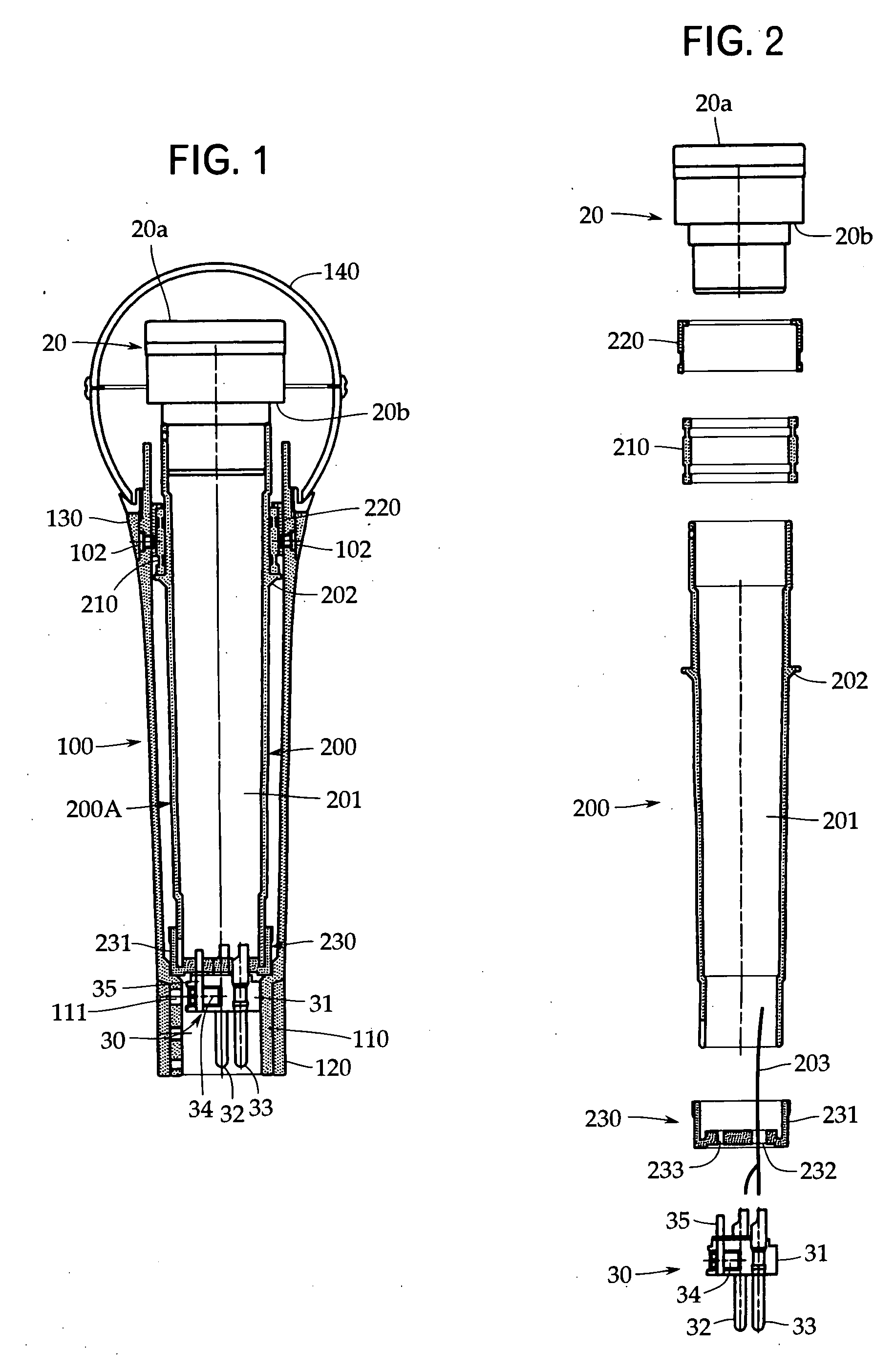
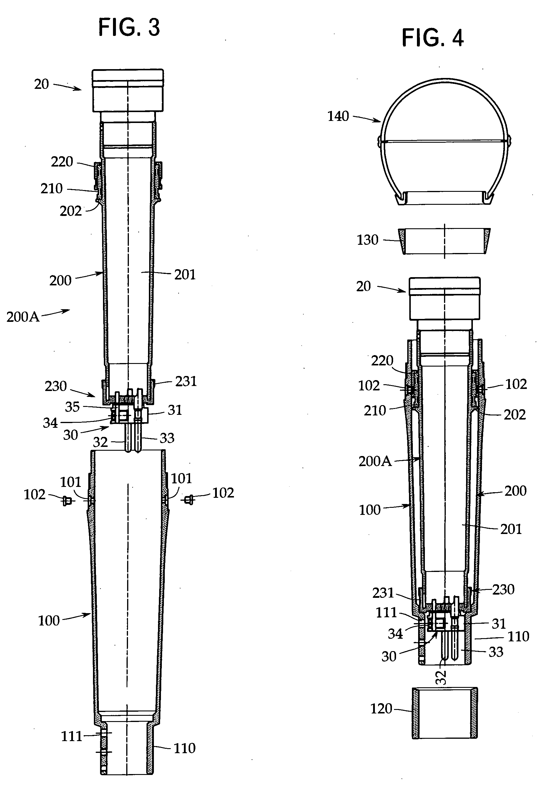
[0019] An embodiment of the present invention will now be described with reference to FIGS. 1 to 4. The present invention is not limited to this embodiment. FIG. 1 is a sectional view of a unidirectional dynamic microphone in accordance with the present invention, and FIGS. 2 to 4 are exploded sectional views showing an assembling procedure.

[0020] First, referring to FIG. 1, the unidirectional dynamic microphone in accordance with the present invention includes a grip housing 100, a cavity sleeve 200, a microphone unit 20, and an output connector 30. The microphone unit 20 and the output connector 30 may be the same as those used in the conventional example explained before with reference to FIG. 5.

[0021] Specifically, because of being unidirectional, the microphone unit 20 is provided with a front audio terminal 20a and a rear audio terminal 20b. Also, although not shown, because of being of a dynamic type, the microphone unit 20 incorporates a diaphragm fitted with a voice coil ...


PUM


Abstract

There is provided a unidirectional dynamic microphone provided with an air chamber for a microphone unit in a grip housing thereof, in which even if an external force is applied to the grip housing, the volume of the air chamber does not change, and also the assembling/disassembling of the microphone can be performed easily. In the unidirectional dynamic microphone in which the grip housing 100 formed in a cylindrical shape is provided; on one end side of the grip housing 100, the microphone unit 20 is supported, and on the other end side thereof, an output connector 30 is mounted; and an air chamber 201 included as a part of an audio circuit of the microphone unit 20 is provided in the grip housing 100, a cylindrical cavity sleeve 200 is provided which is supported in the grip housing 100 via shock mount members 210 and 231 exhibiting rubber elasticity and the interior of which is hollow to form the air chamber 201 for the microphone unit 20.

Description

TECHNICAL FIELD [0001] The present invention relates to a unidirectional dynamic microphone. More particularly, it relates to a configuration of an air chamber in a grip housing, which is included as a part of an audio circuit of a dynamic microphone unit. BACKGROUND ART [0002] As described in Patent Document 1 (Japanese Patent Application Publication No. H5-49090), one of factors for determining the frequency characteristic of a unidirectional dynamic microphone is an air chamber. In a handheld microphone, for example, for vocal use, the air chamber is usually provided in a grip housing formed in a cylindrical shape. One example of such a microphone is explained with reference to FIG. 5. [0003] In a handheld unidirectional dynamic microphone, a grip housing 10 formed in a cylindrical shape by, for example, die casting is provided, and a microphone unit 20 is supported on one end side thereof. Although not shown, the microphone unit 20 incorporates a diaphragm fitted with a voice co...

Claims


Application Information

Patent Timeline
Patent Type & Authority Applications(United States)
IPC IPC(8): H04R9/08H04R1/02H04R1/04H04R1/08H04R1/38H04R25/00
CPCH04R1/083
Inventor AKINO, HIROSHI
Owner AUDIO-TECHNICA
Why Eureka
Try Eureka