High density card retention device

a card retention and high density technology, applied in the field of high density card retention, can solve the problems of not providing vibration or shock resistance in general, not supporting thermal transfer to a heat sink, and the edge connector, etc., to achieve the effect of avoiding non-optimal compression force, large size, and inability to support fine-pitch mounting

Inactive Publication Date: 2009-01-27
BAE SYST INFORMATION & ELECTRONICS SYST INTERGRATION INC
View PDF34 Cites 18 Cited by
  • Summary
  • Abstract
  • Description
  • Claims
  • Application Information

AI Technical Summary

Benefits of technology

[0022]A high-density card retention system that addresses all of the aforementioned problems includes two parts. The first is a tapered channel or slot in the chassis and the second is a mating wedge that runs the length of the channel. The taper and wedge are such that when the wedge is drawn towards the channel it moves towards an opposing channel wall to sandwich and clamp the entire card edge to the opposing wall. This provides clamping pressure along the entire edge of the card to promote efficient heat transfer to the chassis as well as providing robust mechanical mounting.
[0028]Thus, the disadvantage of the relatively thick multi-piece wedge locks and their inability to support fine-pitch mounting, along with non-optimal compression force is avoided because of the large size of the wedge locks. Chassis walls have been limited to bent sheet metal to attempt to actuate the fine pitch. However, the bent sheet metal does not offer high compression forces or large heat transfer area due to the thin cross-section. This in turn results in high thermal resistance. In the subject invention, relatively thick chassis walls can be provided and still retain a fine pitch. Moreover, the subject two-part system provides a universal retention system that does not require edge assemblies to be first attached to the printed circuit cards. In the subject system, the wedge straight wall line contact with the entire edge of the card provides maximal thermal transfer and maximal mechanical stability while at the same time providing for high-density card retention.
[0029]In summary, a two-part, high-density card retention system includes a tapered channel in a chassis or housing and a mating wedge that runs the length of the housing, with the lead wedge being cammed towards a flat channel surface by drawing the wedge inwardly and locating the edge of the board to be mounted between the wedge and the opposing straight channel wall. The mounting provides continuous high-pressure contact between the board and the straight channel wall for maximal thermal transfer and robust anti-vibration and anti-shock mounting of the board to the chassis. Because no additional assemblies are mounted to the edge of the board, the boards may be spaced apart by a fine pitch, thus to minimize the size of the module into which the boards are mounted.

Problems solved by technology

Edge connectors, while protecting electrical contact, do not in general provide vibration or shock resistance, nor do they support thermal transfer to a heat sink.
As electronics are available in smaller and smaller sizes that perform more and more functions, there is a tradeoff between power and size.
Additionally, decreasing size may result in increased power consumption that drives the operating temperature of the electronics up.
Oftentimes ambient air at the board is not enough to dissipate the heat generated by the components on the board.
As can be readily seen, there is a correspondence between the amount of signal processing that is performed and required heat dissipation, with heat buildup being a significant failure mode for these circuits.
The problems with such wedge lock assemblies are two-fold, first having to do with the heat transfer efficiency and secondly, the size of the wedge lock assemblies that are mounted to the edges of the circuit cards.
For board re-spinning or replacement, if one wishes to switch out a circuit card, for instance, that is defective, one needs to mount these wedge lock assemblies to the ends of the new circuit card.
Because of the way in which these wedge lock devices operate, there is thus increased the thermal resistance, which in essence fails to dissipate enough heat.
Since the thermal and physical contact area does not encompass the entire edge of the card, heat transfer and mechanical locking properties are not as robust as they could be.
In summary, the wedge lock type of card mounting assemblies present a barrier to heat transfer, since the temperature flow across each of the spaced-apart trapezoidal surfaces is only some percentage of the total area available.
This discontinuity is believed to be more susceptible to circuit card damage under vibration at the interface of the high pressure / zero pressure zones than a continuously clamped circuit card would experience.
However, this multi-part device offers a high-resistance heat transfer path due to the fact that heat has to go through a thin contacting blade, a cam and a thin wall.
Lastly, prior art devices expand and move away from the circuit card as they are tightened.

Method used


Image

  • High density card retention device
  • High density card retention device
  • High density card retention device

Examples


Embodiment Construction

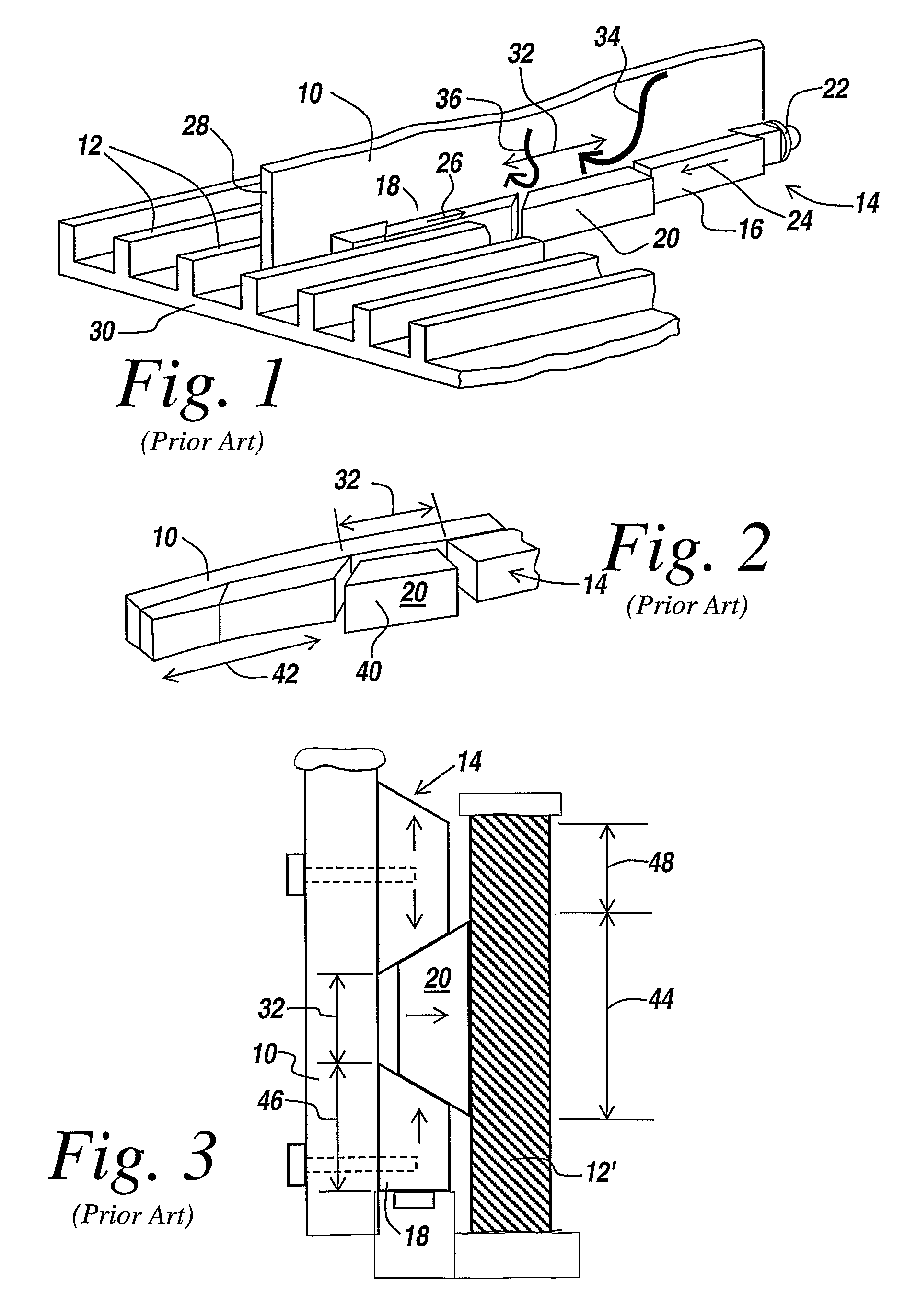
[0040]Referring now to FIG. 1, in the prior art a circuit board 10 is to be clamped to opposed upstanding ridges 12 through the use of a wedge lock assembly 14, which is a multiple-section device including stationary sections 16 and 18 mounted to the board, and a wedge 20, which is moved away from the board when a lead screw 22 is tightened to move sections 16 and 18 in the direction of arrows 24 and 26 respectively. Since the backside of board 10, here illustrated at 28, abuts a rib 12, the movable wedge 20 is moved by the aforementioned lead screw actuation to abut an opposed rib, with the ribs serving to define rectilinear channels in a chassis 30.

[0041]It will be appreciated that with lead screw actuation, wedge 20 moves away from the face of board 10 and contacts the opposing rib. This movement away from the card provides an area of no contact 32 such that heat flow from the board through the wedge lock assembly to the rib and thus the chassis is impeded as illustrated by arrow...


PUM


Abstract

A two-part, high-density card retention system includes a tapered channel in a chassis or housing and a mating wedge that runs the length of the housing, with the lead wedge being cammed towards a flat channel surface by drawing the wedge inwardly and locating the edge of the board to be mounted between the wedge and the opposing straight channel wall. The mounting provides continuous high-pressure contact between the board and the straight channel wall for maximal thermal transfer and robust anti-vibration and anti-shock mounting of the board to the chassis. Because no additional assemblies are mounted to the edge of the board, the boards may be spaced apart by a fine pitch, thus to minimize the size of the module into which the boards are mounted.

Description

RELATED APPLICATIONS[0001]This application claims rights under 35 USC § 119(e) from U.S. Application Ser. No. 60 / 682,756 filed May 19, 2005, the contents of which are incorporated herein by reference.STATEMENT OF GOVERNMENT INTEREST[0002]This invention was made with United States Government support under Contract No. 03-C-8308. The United States Government has certain rights in this invention.FIELD OF THE INVENTION[0003]This invention relates to printed circuit card retention and more particularly to securing a printed circuit card to a chassis to assure maximum thermal transmission to the chassis and for robust high-density card retention.BACKGROUND OF THE INVENTION[0004]Printed circuit cards have been mounted to a chassis or heat sink with devices that are mounted to the printed circuit card and which, when actuated, retain the edge of the circuit card in a slot in a chassis, housing or other circuit card-retaining frame. The printed circuit cards have also been mounted to a frame...

Claims


Application Information

Patent Timeline
Patent Type & Authority Patents(United States)
IPC IPC(8): H05K7/20F16B2/14
CPCH05K7/1404Y10T403/76
Inventor MILLER, RICHARD D.WACHSMAN, ADAM D.
Owner BAE SYST INFORMATION & ELECTRONICS SYST INTERGRATION INC
Why Eureka
Try Eureka