Techniques for improving pressure sensor shock robustness in fluid containment devices

a technology of shock robustness and pressure sensor, which is applied in the field of inkjet printing, can solve the problems of general inability to predict the condition of ink in the ink container, printhead damage, and time wasted in operating the printer without achieving a complete printed imag

Inactive Publication Date: 2005-05-03
HEWLETT PACKARD DEV CO LP
View PDF13 Cites 19 Cited by
  • Summary
  • Abstract
  • Description
  • Claims
  • Application Information

AI Technical Summary

Problems solved by technology

A consideration with ink jet printing systems that employ ink containers that are separate from the printheads is the general inability to predict an out of ink condition for an ink container.
Otherwise, printhead damage may occur as a result of firing without ink, and / or time is wasted in operating a printer without achieving a complete printed image, which is particularly time consuming in the printing of large images which often are printed in an unattended manner on expensive media.
A challenge for ink cartridges with integrated pressure sensors is protecting the sensor from pressure spikes, which commonly occur during manufacturing, shipping or handling, and can occur due to dropping the cartridge.

Method used


Image

  • Techniques for improving pressure sensor shock robustness in fluid containment devices
  • Techniques for improving pressure sensor shock robustness in fluid containment devices
  • Techniques for improving pressure sensor shock robustness in fluid containment devices

Examples


Embodiment Construction

[0028]In the following detailed description and in the several figures of the drawing, like elements are identified with like reference numerals.

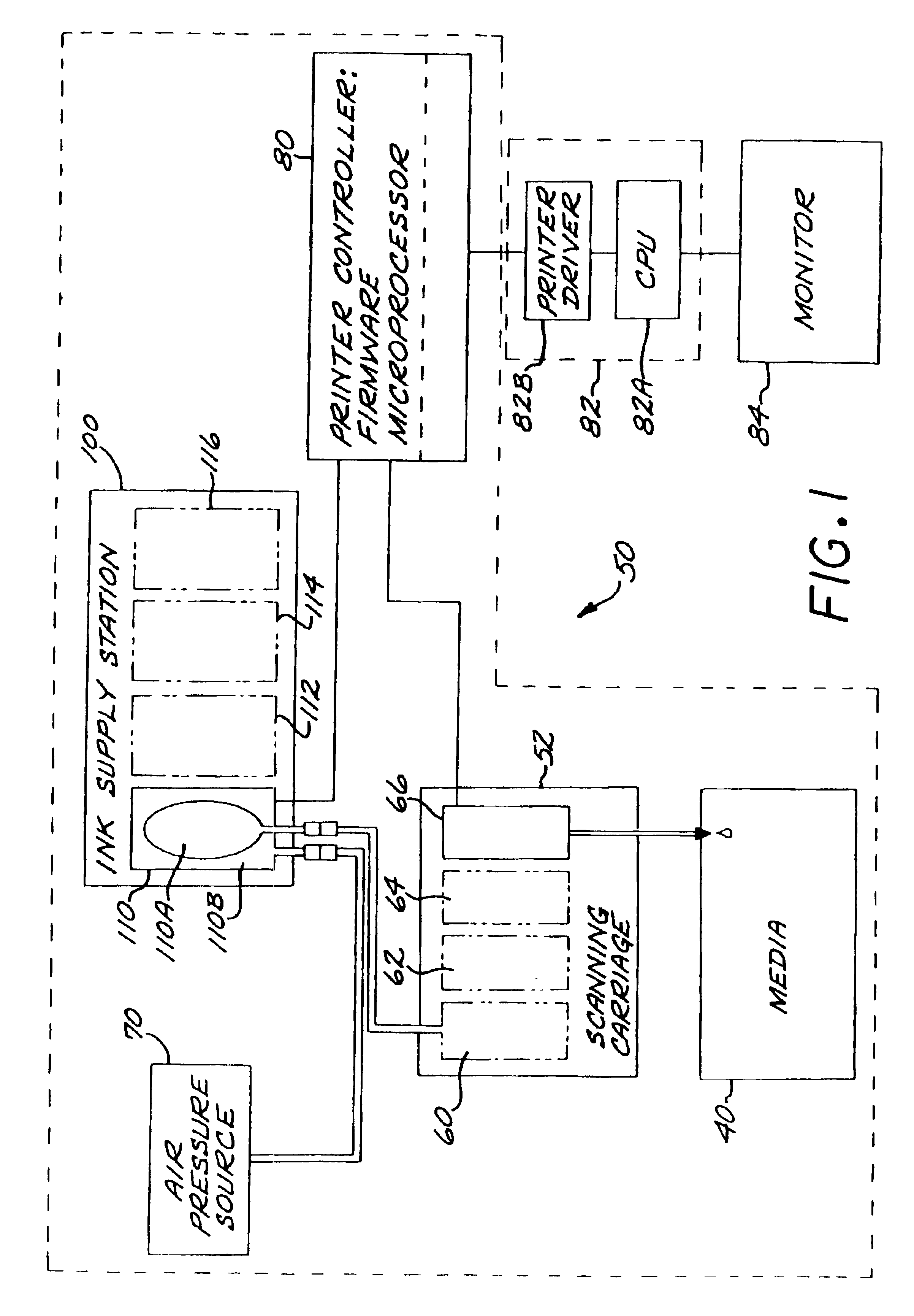
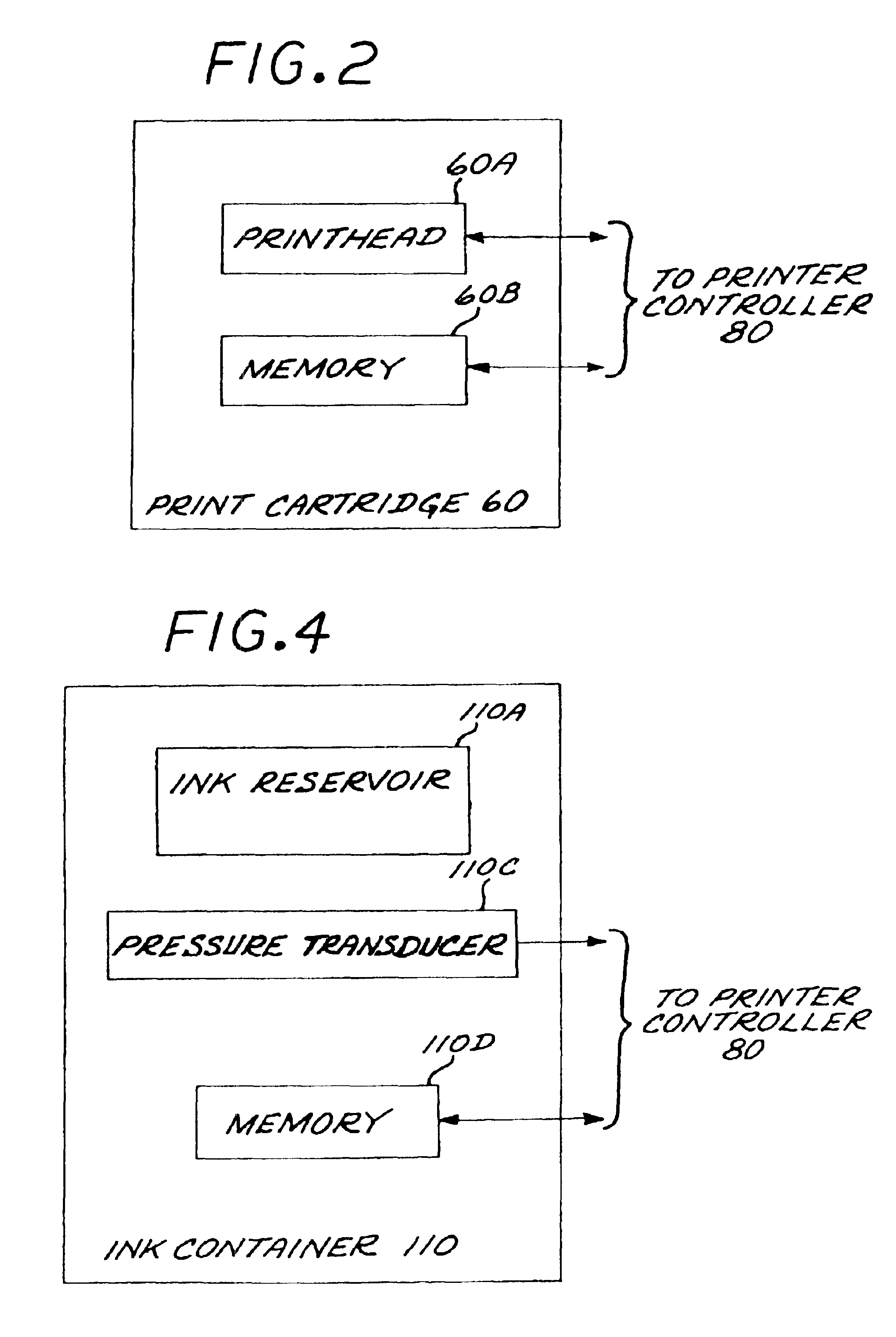
[0029]Referring now to FIG. 1, set forth therein is a schematic block diagram of an exemplary printer / plotter 50 in which the invention can be employed. A scanning print carriage 52 holds a plurality of print cartridges 60-66 which are fluidically coupled to an ink supply station 100 that supplies pressurized ink to the print cartridges 60-66. By way of illustrative example, each of the print cartridges 60-66 comprises an ink jet printhead and an integral printhead memory, as schematically depicted in FIG. 2 for the representative example of the print cartridge 60 which includes an ink jet printhead 60A and an integral printhead memory 60B. Each print cartridge has a fluidic regulator valve that opens and closes to maintain a slight negative gauge pressure in the cartridge that is optimal for printhead performance. The ink provided to each ...


PUM

PropertyMeasurementUnit
sizeaaaaaaaaaa
sizeaaaaaaaaaa
pore sizesaaaaaaaaaa

Abstract

Techniques are disclosed for improving pressure sensor shock robustness in fluid containment devices by providing a mechanical filter configured to prevent high-frequency pressure shocks from damaging the pressure sensor. One approach includes a body of elastomeric material disposed on an external surface of the sensor. Another approach is a porous plug in a fluid pathway leading to the sensor. Yet another approach is to provide a seal structure with a labyrinth fluid path.

Description

BACKGROUND OF THE DISCLOSURE[0001]The art of inkjet printing is relatively well developed. Commercial products such as computer printers, graphics plotters, and facsimile machines have been implemented with ink jet technology for producing printed media. Generally, an ink jet image is formed pursuant to precise placement on a print medium of ink drops emitted by an ink drop generating device known as an ink jet printhead. Typically, an ink jet printhead is supported on a movable carriage that traverses over the surface of the print medium and is controlled to eject drops of ink at appropriate times pursuant to command of a microcomputer or other controller, wherein the timing of the application of the ink drops is intended to correspond to a pattern of pixels of the image being printed.[0002]Some known printers make use of an ink container that is separably replaceable from the printhead. When the ink container is exhausted it is removed and replaced with a new ink container. The us...

Claims


Application Information

Patent Timeline
Patent Type & Authority Patents(United States)
IPC IPC(8): B41J2/175G01F23/14
CPCB41J2/175B41J2/17509B41J2/17513G01F23/14B41J2/17546B41J2/17556B41J2/17523
Inventor MALIK, CRAIGARDITO, MICHAEL S.BURKUM, PHILIPWILSON, RHONDA L.
Owner HEWLETT PACKARD DEV CO LP
Why Eureka
Try Eureka