
Cleaning apparatus for electrodes of optical fiber fusion splicer

a cleaning apparatus and electrode technology, applied in the direction of cleaning process and apparatus, chemistry apparatus and processes, instruments, etc., can solve the problems of failure of the shape accuracy of the electrode tip end, product rejection, and inability to achieve normal fusion splicing, so as to facilitate cleaning operation.

Inactive Publication Date: 2005-05-03
THE FUJIKURA CABLE WORKS LTD
View PDF5 Cites 1 Cited by
  • Summary
  • Abstract
  • Description
  • Claims
  • Application Information

AI Technical Summary

Benefits of technology

[0010]The tip end of the electrode is rubbed with the brush body so that any extraneous substances are removed therefrom. The tip end of the electrode is prevented from asymmetric deformation because the tip end is rubbed axis-symmetrically and is prevented from scratching because there is no use of an edge tool. Furthermore the cleaning operation is easily achieved simply by pressing the electrode into the brush body. The electrode is recovered so as to be reused with the easy operation, thereby the electrode may be reused until it has been worn off.
[0012]According to the constitution, in addition to the effect according to the first aspect, the electrode is positioned coaxially with the rotation axis when fixed to the chuck thereby an eccentric rotation thereof is prevented. Therefore the cleaning operation is further made easier.

Problems solved by technology

According to the proposed fusion splicer described above, arc discharges have a tendency of the shape or position thereof changing after discharging several times. In that case, fusion splicing cannot be accomplished normally because heat is applied to an inadequate position of the optical fibers, and, in severe cases, the product may be rejected.
However, the tip ends of the electrodes are easily deformed or scratched with the edge tool, therefore the cleaning operation causes a failure of the shape accuracy of the electrode tip end.
Thus the electrodes often need to be changed, and it raises production costs.
This operation damages the productivity of the fusion splicing.

Method used


Image

  • Cleaning apparatus for electrodes of optical fiber fusion splicer
  • Cleaning apparatus for electrodes of optical fiber fusion splicer
  • Cleaning apparatus for electrodes of optical fiber fusion splicer

Examples


first embodiment

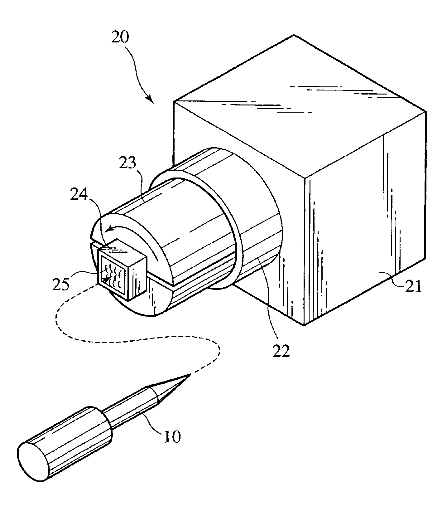
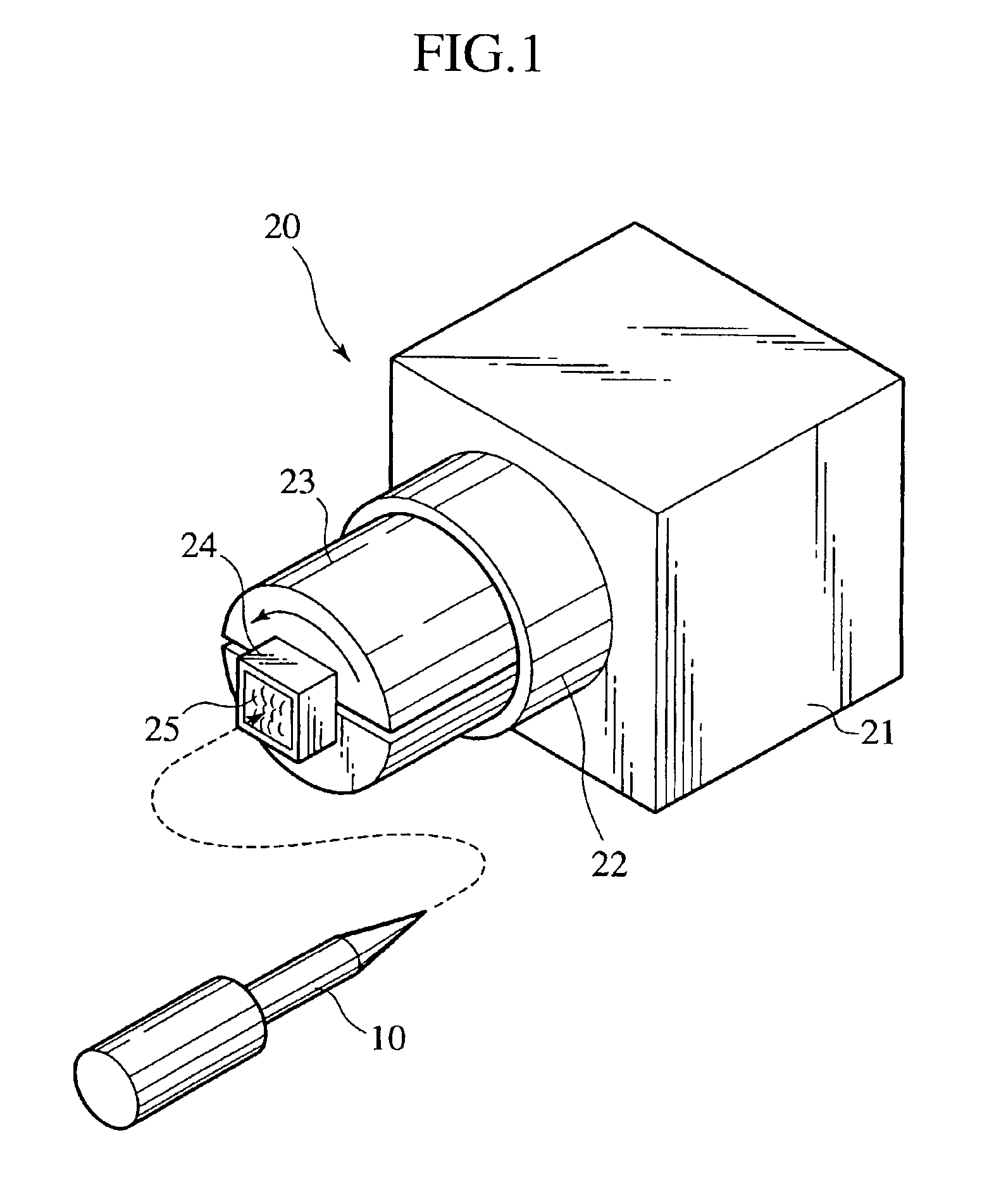
[0016]the present invention is described hereinafter with reference to FIG. 1.

[0017]The cleaning apparatus 20 according to the present invention comprises a chassis 21 housing a motor (not shown); a chuck 23 engaged with a rotation axis 22 of the motor; and a supporting container 24 fixed to the chuck 23. The chuck 23 may be inserted into and engaged with the rotation axis 22, and may be extracted and detached therefrom. A brush body 25 is replaceably filled in the supporting container 24. As the brush body 25, a steel wool and a nylon brush are preferably exemplified. The supporting container 24 of the brush body 25 is shaped to be, for example, an angular tube so as not to rotate the brush body 25 in relation to the supporting container 24. The supporting container 24 is fixed to the chuck 23 and the chuck 23 is further inserted into the rotation axis 22 so as to be engaged.

[0018]In a case where an electrode 10 needs to be cleaned, a tip end thereof may be inserted into the brush ...

second embodiment

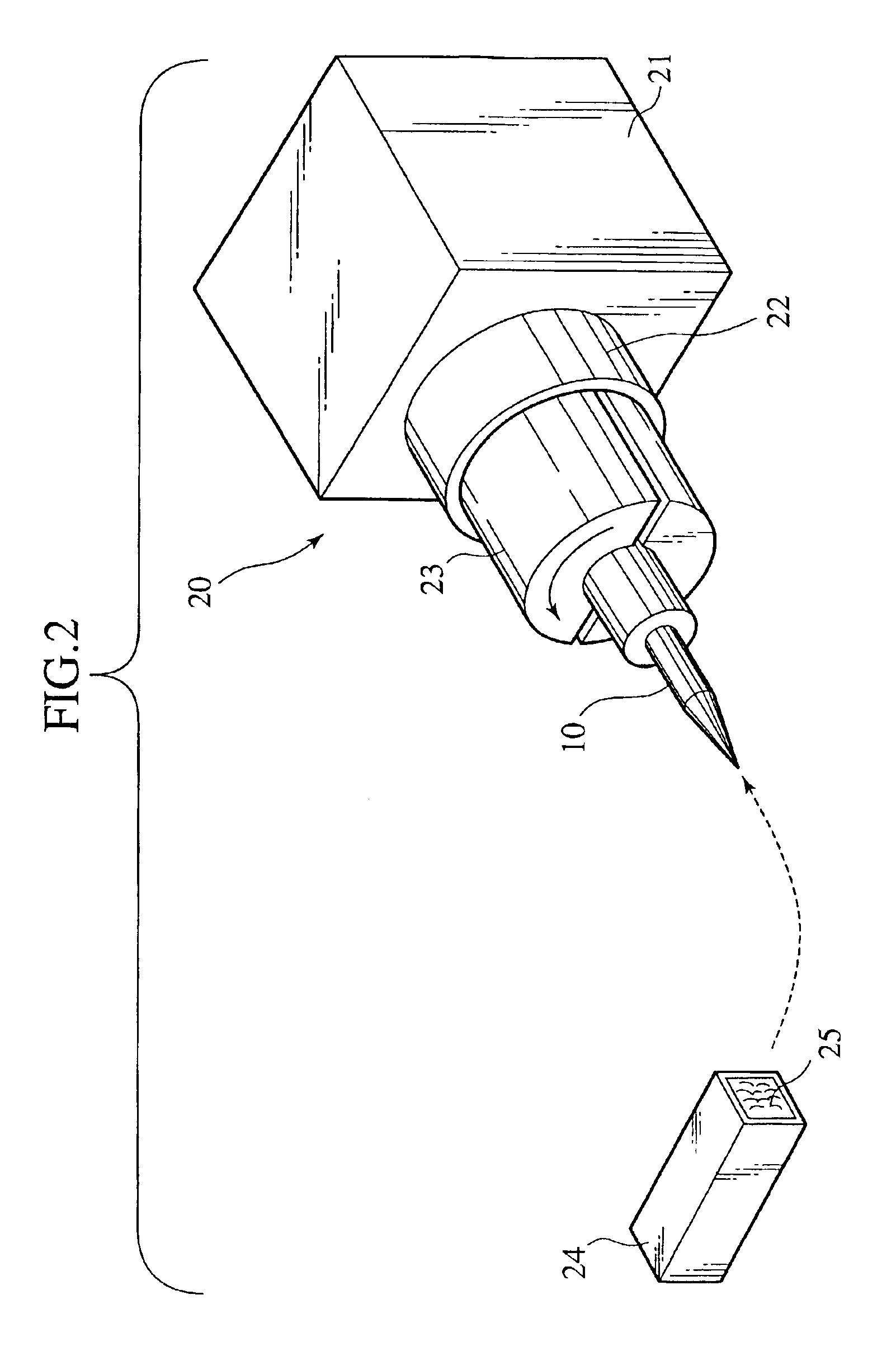
[0020]the present invention is described hereinafter with reference to FIG. 2.

[0021]According to the second embodiment, in contrast with the first embodiment, the brush body 25 is fixed and the electrode 10 rotates. The electrode 10 is fixed to the chuck 23 at the proximal end thereof and rotates in connection with the rotation axis 22. The supporting container 24 filled with the brush body 25 may be supported appropriately with hands and the like.

[0022]The electrode 10, when cleaning, is detached from the optical fiber fusion splicer and the proximal end thereof is fixed to the chuck 23. And the chuck 23 is inserted to the rotation axis so as to be engaged therewith. Next, the supporting container 24 is supported with hands and the like and the brush body 25 is pressed to the end tip of the electrode 10 so that the tip end of the electrode 10 is closely covered therewith. In that condition, the motor housed in the chassis 21 drives the rotation axis 22 to rotate so that the brush b...


PUM


Abstract

The cleaning apparatus for electrodes includes a supporting container provided with a replaceable brush body; and a rotation mechanism for the rotation of the supporting container. The brush body accepts the insertion of the electrodes and cleans the tip end thereof by rotation.

Description

BACKGROUND OF THE INVENTION[0001]1. Field of the Invention[0002]The present invention relates to a cleaning apparatus for electrodes applied to an optical fiber fusion splicer.[0003]2. Description of the Related Art[0004]An optical fiber fusion splicer comprises a pair of blocks on which two optical fibers are placed respectively, a pair of electrodes which generates an arc discharge therebetween so as to fuse and splice the optical fibers. A tip end of each electrode is of a tapered shape so as to generate an arc discharge easily and the electrodes are connected to a power source device which generates high voltage. The tapered shape of the tip ends of the electrodes are shaped precisely to achieve a correct splicing of fine optical fibers. The fusion splicer is housed in an appropriate chassis.[0005]Fusion splicing of optical fibers is described as follows. First, two optical fibers are fixed on the respective blocks and the tip ends thereof are contacted mutually. Second, the pai...

Claims


Application Information

Patent Timeline
Patent Type & Authority Patents(United States)
IPC IPC(8): B08B1/04B08B1/00G02B6/36G02B6/255
CPCB08B1/00G02B6/2551B08B1/04B08B2240/02B08B1/32B08B1/165
Inventor IWASHITA, YOSHINORIOKUBO, AKIRASATO, TAKESHI
Owner THE FUJIKURA CABLE WORKS LTD
Learn More