
Debris separation and filtration systems

a filtration system and debris technology, applied in the field of debris separation and filtration systems, can solve the problems of increasing the cost of the system, the likelihood of system failure, and the effective filter life and efficiency of serial cyclone separator/baghouse filter systems that are often shorter than the period of desired operation, and achieves the effect of substantially reducing the speed of centrifugal airflow

Inactive Publication Date: 2005-05-03
FEDERAL SIGNAL CORPORATION
View PDF104 Cites 51 Cited by
  • Summary
  • Abstract
  • Description
  • Claims
  • Application Information

AI Technical Summary

Benefits of technology

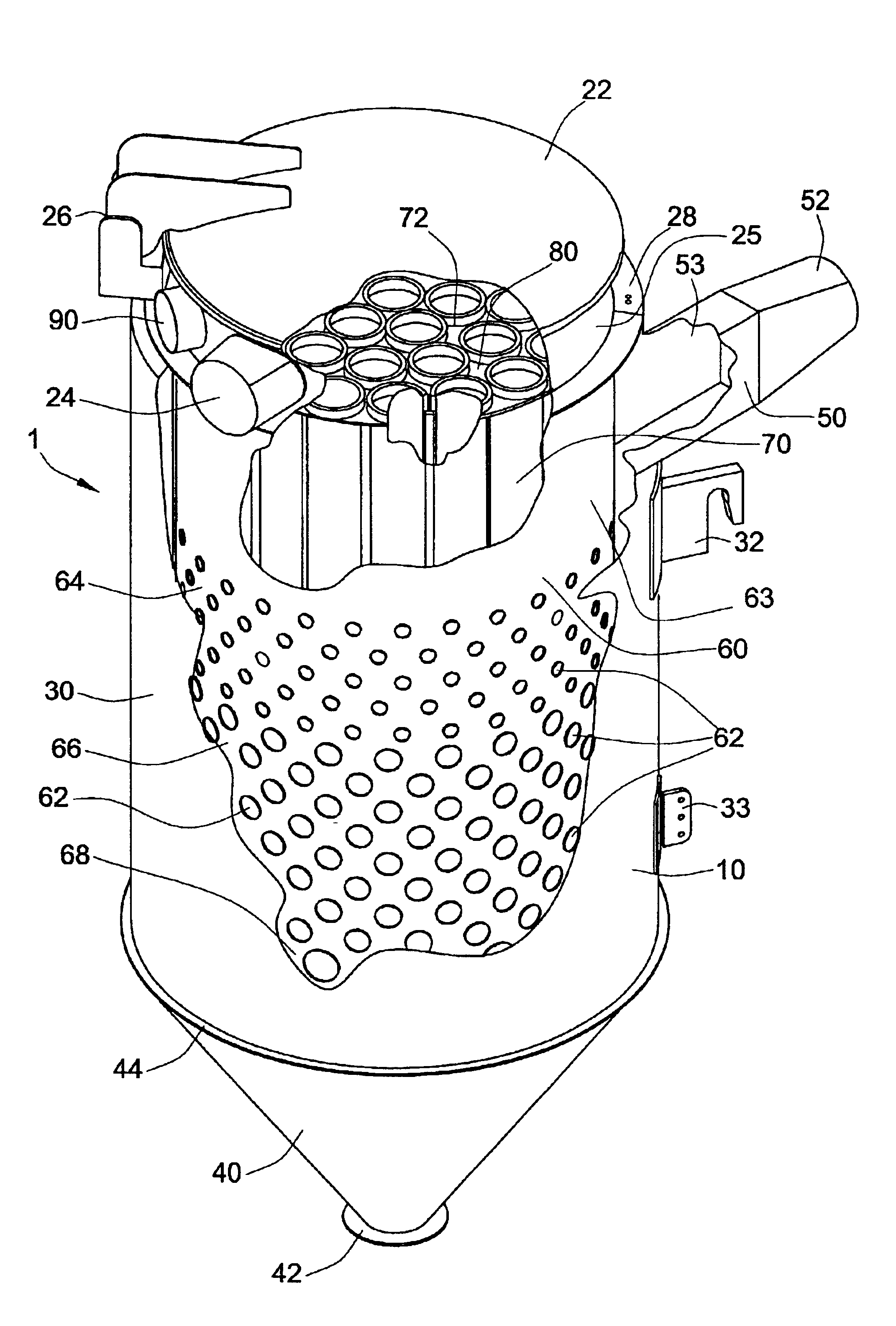
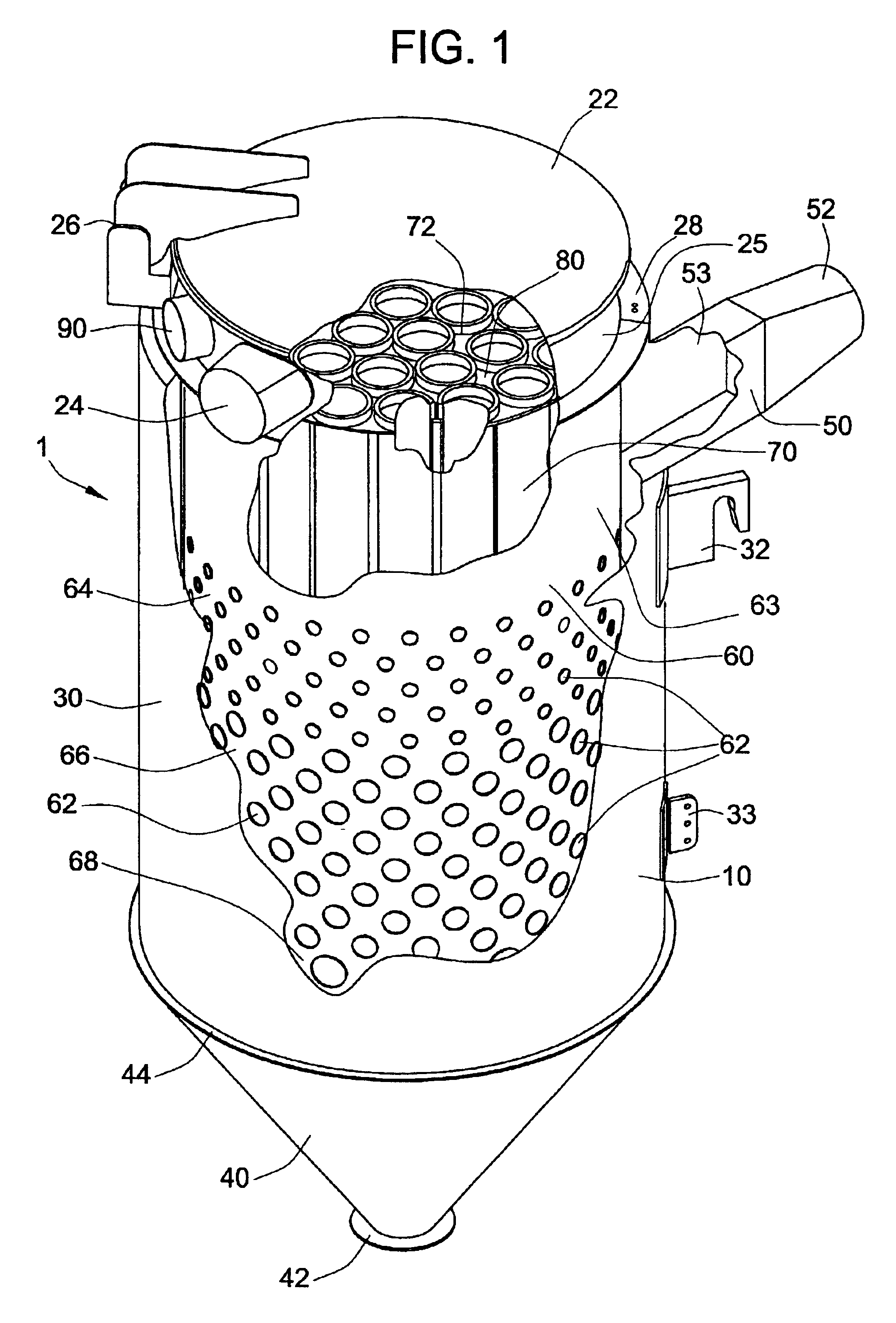
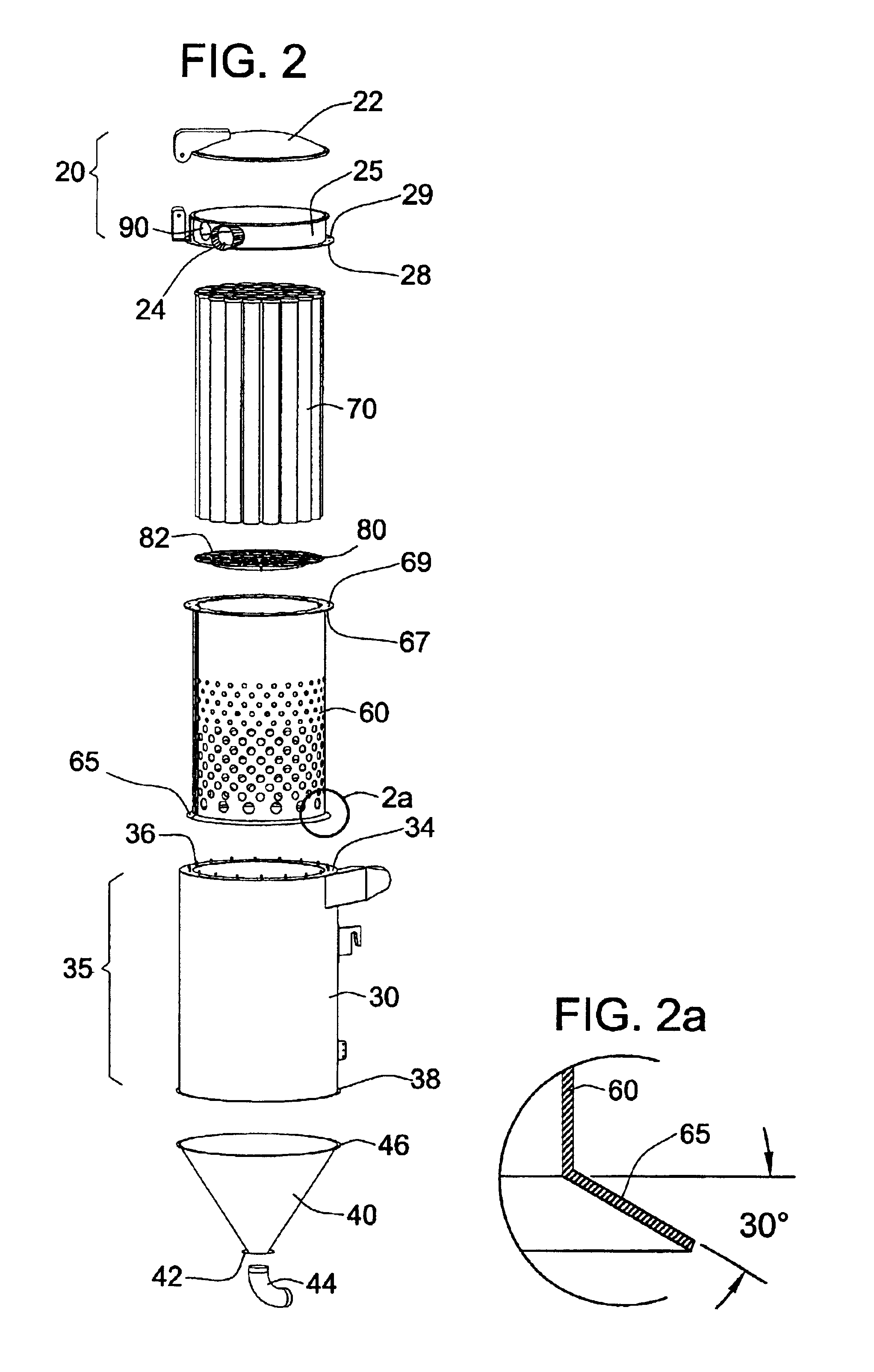
[0011]In alternative or related aspects, the invention provides a debris separation-filtration unit including a housing, an inlet, an inner shell, and a filter, as described above, characterized in that the housing includes a bottom debris collecting portion; a middle portion, at least a part of which middle portion is defined by the cylindrical sidewall; and a top portion. In such debris separation and filtration units, the inlet

Problems solved by technology

However, lighter debris particles remain in the air stream and continue to move toward the blower and the exhaust where the air stream is released to the environment.
Unfortunately, in practice most shaker and agitator systems have been shown to make only modest improvements in filter life.
Moreover, such systems may require a large number of mechanical and / or pneumatic components and thereby increase the cost of the system as well as the likelihood of system failure.
While effective in many respects, the effective filter life and efficiency in such serial cyclone separator / baghouse filter systems still often remains shorter than the period of desired operation.

Method used


Image

  • Debris separation and filtration systems
  • Debris separation and filtration systems
  • Debris separation and filtration systems

Examples


Embodiment Construction

[0032]The invention provides combined debris centrifugal separation and filtration devices (units) and debris collection, separation, and filtration systems, some of which systems are characterized in including one or more of such separation-filtration units. The debris separation-filtration units and systems of the invention are useful as, or as part of, stationary and mobile debris collection systems.

[0033]In one exemplary aspect, the invention provides a debris separation-filtration unit that includes a housing; an inlet port that receives debris-laden air and delivers the air in a tangential, centrifugal airflow-forming manner to the interior of housing when a sufficient airflow is present; an inner shell enclosed within the housing that includes a number of airflow passageways; and a debris-capturing filter, which filter also is enclosed within the housing in a position such that the sides of the filter are at least substantially surrounded by the inner shell. Due to the format...


PUM

PropertyMeasurementUnit
Fractionaaaaaaaaaa
Fractionaaaaaaaaaa
Diameteraaaaaaaaaa

Abstract

The invention provides a debris separation-filtration unit comprising a housing; an inlet that receives debris-laden air delivers the air in a tangential, centrifugal airflow-forming manner to the interior of housing; an inner shell that includes a number of airflow passageways; and a debris-capturing filter, the sides of which filter are at least substantially surrounded by the inner shell. Due to the formation of the centrifugal airflow and presence of the inner shell in the housing, only a portion of the debris particles entering the unit come in contact with the filter. The invention also provides debris collection, separation, and filtration systems comprising one or more of the separation-filtration units of the invention; debris collection vehicles comprising one or more of such units or systems; and related methods of collecting, separating, and filtering debris.

Description

FIELD OF THE INVENTION[0001]This invention pertains to systems for collecting, separating, and filtering debris, debris collection vehicles comprising such systems, and related methods of collecting, separating, and filtering debris.BACKGROUND OF THE INVENTION[0002]Stationary and mobile vacuum debris collection systems have proven to be useful in a number of industrial and environmental applications. For example, truck-mounted vacuum cleaning systems have long been used to clean a wide variety of debris from areas such as waste collection areas of power plants, steel mills, and other industrial sites.[0003]Typically, vacuum debris cleaning systems have one or more collection chambers into which collected debris material is deposited (such debris collection tanks or hoppers are commonly referred to as “debris bodies” in the art). A high velocity blower or fan generates a stream of air to flow through a flexible hose that induces the debris to flow from the debris collection site thro...

Claims


Application Information

Patent Timeline
IPC IPC(8): B01D50/00E01H1/00E01H1/08
CPCE01H1/0827B01D50/002B01D50/20
Inventor STRAUSER, DANIEL P.TROUTT, SEAN STUARTSTEIN, PHILIP WAYNE
Owner FEDERAL SIGNAL CORPORATION
Learn More