Apparatus for treating cytological or histological specimens

a technology for cytological or histological specimens, applied in the field of apparatus for treating objects, can solve the problems of inability to move unrestrictedly, inability to position and/or pick up samples, and inability to use corresponding motion mechanisms, etc., to achieve maximum flexibility, simple design, and contribute to the flexibility of the apparatus

Inactive Publication Date: 2005-05-03
LEICA BIOSYST NUSSLOCH
View PDF10 Cites 38 Cited by
  • Summary
  • Abstract
  • Description
  • Claims
  • Application Information

AI Technical Summary

Benefits of technology

[0014]It is furthermore conceivable for the linear shaft to be shiftable or movable in its position inside the baseplate or inside the housing of the apparatus. For that purpose, the linear shaft could be displaceable, preferably between the processing stations, along a rail or in the manner of an X-Y coordinate stage. A stationary configuration of the linear shaft is also conceivable, and is particularly simple in terms of design and therefore advantageous.
[0015]Concretely, the robot arm could comprise two partial arms joined pivotably to one another, so that assuming a rotary motion at the linear shaft and assuming a pivotable configuration of both partial arms, all desired positions are reachable. Assuming the height adjustment of the gripper already mentioned earlier, the latter can be positioned at any desired point in three dimensions, thus achieving a maximum degree of flexibility.
[0016]The partial arms of the robot arms, and optionally the gripper, could be rotationally driven via drive belts, the rotational drive being associated with the respective partial arm or with the partial arm that is rotatably associated with the linear shaft. For example, it is conceivable for the partial arm articulated on the linear shaft to have associated with it single common drive for rotating or pivoting the two partial arms, and optionally for rotating and / or actuating the gripper. Alternatively, it is possible for the partial arm articulated on the linear shaft to have associated with it preferably two independent drives for rotating or pivoting the two partial arms and optionally for rotating and / or actuating the gripper. This, too, contributes to the flexibility of the apparatus as a whole.

Problems solved by technology

The aforementioned motion mechanisms are problematic in practical use, however, in that the samples to be positioned and / or picked up cannot be moved unrestrictedly.
The use of corresponding motion mechanisms is thus greatly limited, or the use of such motion mechanisms requires a very particular (and rigid) arrangement of the processing stations.

Method used


Image

  • Apparatus for treating cytological or histological specimens
  • Apparatus for treating cytological or histological specimens
  • Apparatus for treating cytological or histological specimens

Examples


Embodiment Construction

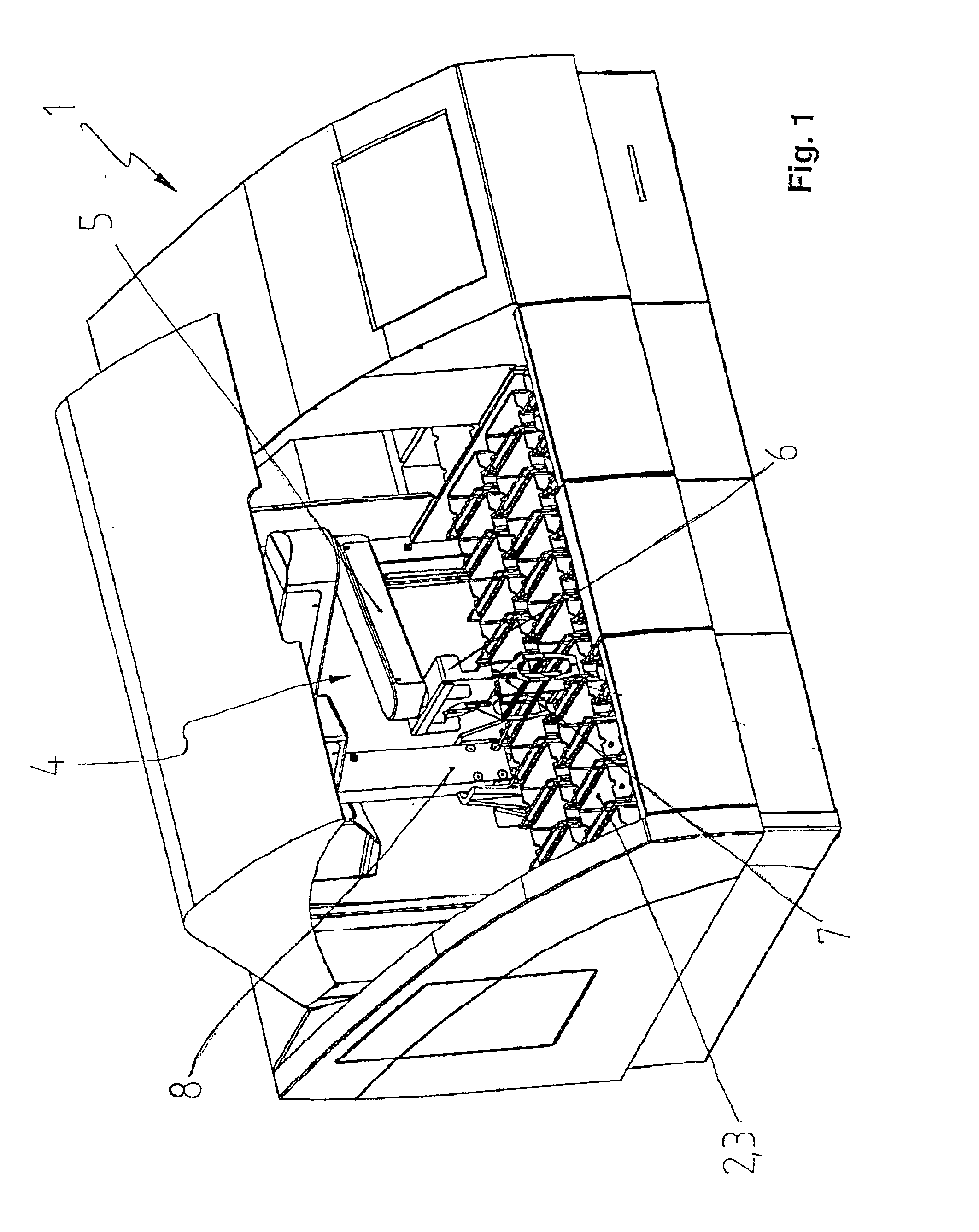
[0028]FIG. 1 shows, in a schematic view, an exemplary embodiment of an apparatus according to the present invention for treating cytological or histological specimens, this being concretely an automatic stainer 1. Regarding the basic construction of an automatic stainer, the reader is referred to EP 0 849 582 A2.

[0029]Automatic stainer 1 comprises multiple processing stations 2, these being defined here by vessels 3 for liquids or reagents.

[0030]Also provided is a transport device 4 which moves objects (not shown in the Figures) into and out of processing stations 2.

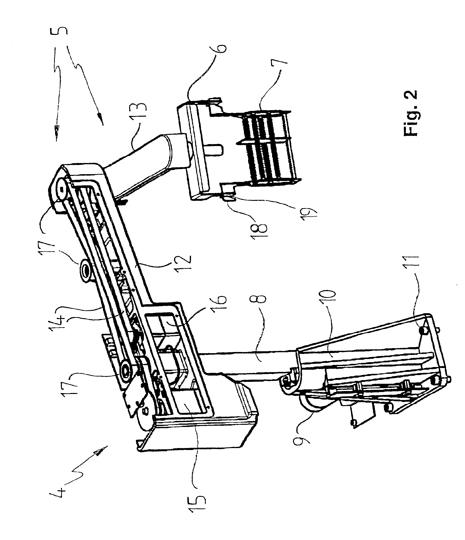
[0031]According to the present invention, transport device 4 comprises a robot arm 5 that is movable in three dimensions and provides for arbitrary positioning of the objects. Said robot arm 5 ensures the greatest possible flexibility for transport device 4, specifically in that arbitrary positioning of the objects in three dimensions (i.e., concretely, inside the apparatus) is possible.

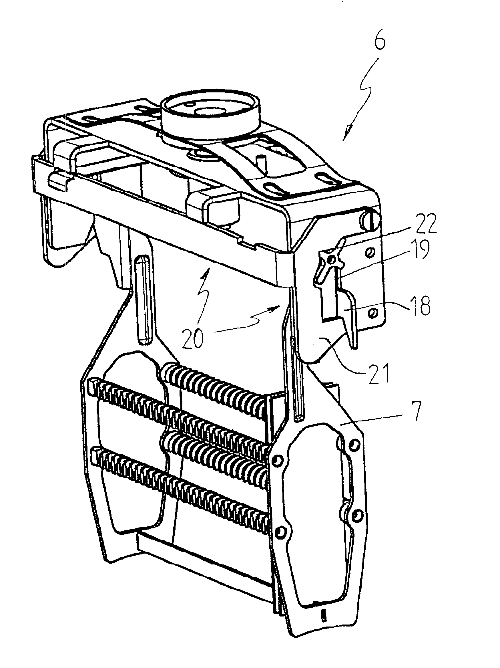
[0032]Also evident from FIG. 1 is ...


PUM

PropertyMeasurementUnit
sizeaaaaaaaaaa
heightaaaaaaaaaa
degree of flexibilityaaaaaaaaaa

Abstract

An apparatus for treating objects, in particular cytological or histological specimens, having multiple processing stations (2) and a transport device (4) for delivering the objects into and out of the processing stations (2), is characterized in that the transport device (4) comprises a robot arm (5) that is movable in three dimensions and provides for arbitrary positioning of the objects.

Description

CROSS REFERENCE TO RELATED APPLICATIONS[0001]This invention claims priority of the German patent application 100 41 231.9 filed Aug. 22, 2000 which is incorporated by reference herein.FIELD OF THE INVENTION[0002]The invention concerns an apparatus for treating objects, in particular cytological or histological specimens, having multiple processing stations and a transport device for delivering the objects into and out of the processing stations.BACKGROUND OF THE INVENTION[0003]Apparatuses of the generic type are known from a wide variety of fields. Very generally, they are apparatuses used for handling and / or processing objects of any kind. The objects are delivered either to a single processing station or to multiple processing stations, usually in a predefined sequence; processed therein; and then lastly transported away from the processing station, in which context different groups of processing stations can be arranged behind and / or next to another.[0004]The reader is referred, ...

Claims


Application Information

Patent Timeline
Patent Type & Authority Patents(United States)
IPC IPC(8): G01N1/30G01N1/31G01N33/48G01N1/36
CPCG01N1/31G01N2001/315
Inventor WERNZ, MARTINTHIEM, STEFANBARTH, ERIC
Owner LEICA BIOSYST NUSSLOCH
Why Eureka
Try Eureka