Screen formed from a stretched flexible surface bearing a print

a flexible surface and print technology, applied in the field of stretched flexible surfaces, can solve the problems of insufficient mechanical stability, inability to give precise and clear images, and inability to air-permeate the layer receiving ink, so as to achieve excellent graphic reproduction, resist dirt, and sufficient mechanical stability

Inactive Publication Date: 2005-05-03
CHENEL GUY GILBERT
View PDF7 Cites 3 Cited by
  • Summary
  • Abstract
  • Description
  • Claims
  • Application Information

AI Technical Summary

Benefits of technology

[0012]The present invention seeks to remedy these drawbacks and proposes the development of a decorative screen intended to be installed primarily externally, in which the quality of the graphic reproduction of the image is excellent, which resists dirt and offers a sufficient mechanical stability when the screen is produced with a large surface area.SUMMARY OF THE INVENTION
[0017]The screen according to the invention offers the advantage of having sufficient permeability (of the order of 10% to 20%) to permit a sufficient passage of air so that the resultant of the forces exerted on the screen and consequently on the structure supporting the screen is not excessive.
[0019]The size of the flakes makes it possible to create a good matt surface for inscription or for decoration, giving a precise and clear decoration and retaining all the original quality of the image regardless of the angle at which the screen is viewed. The qualities of the screen are equally ensured by the flatness of the surface formed by the porous superficial coating such that, in contrast to the prior art, the ink jet printing is not made on free fibers directed in three dimensions in the surface layer of the non-woven fabric.
[0023]According to another embodiment the visible section of the fibers of the surface layer or thin layer is increased by producing the fabric from non-woven fibers, at least in part from welded dual-component fibers, ensuring both reinforcement and opacity, that is to say the increase in the visible surface sufficient for printing. The dual-component fibers have a core and a cladding, this latter having a softening point lower than that of the core.
[0024]The fabric is heated to the right temperature in order to obtain welds at the junction of the threads producing a structure which is solid in three dimensions. This non-woven fabric can also be calendered under heat in order to form a thin surface layer of which the visible section at least of certain fibers is increased by crushing combined with welds between the fibers, which will have the effect of tightening the fibers and widening the coatings of the cores of the fibers. This operation preserves the necessary permeability of the whole of the screen.

Problems solved by technology

However, although these known screens which are formed from a non-woven fabric are of more interest than canvas sheets because they necessitate less resistant support structures for stability in the wind, they do nevertheless have a certain number of drawbacks.
First of all, since the material itself is relatively porous it functions as a filter and dirt accumulates in the thickness of the non-woven fabric.
However, such a layer to receive the ink is not air-permeable or at least it is not sufficiently so in order to form an external screen.
Furthermore, ink jet printing, which penetrates more or less and spreads through a relatively substantial thickness of the non-woven fabric, does not give an image which is as precise and clear as one might wish since certain of the printing droplets penetrate too deeply into the non-woven fabric to be perceptible on the exterior.
This can spoil the sharpness of an outline or the colour which is produced by ink jets and results from the combination of primary shades.
Finally, since the ink jets are projected according to a certain firing line, if the image is not viewed from the same angle the image seen will not have the desired sharpness due to this “in depth” printing.
Finally, when these screens have substantial surface areas they lack resistance and can deform or collapse.

Method used


Image

  • Screen formed from a stretched flexible surface bearing a print
  • Screen formed from a stretched flexible surface bearing a print
  • Screen formed from a stretched flexible surface bearing a print

Examples


Embodiment Construction

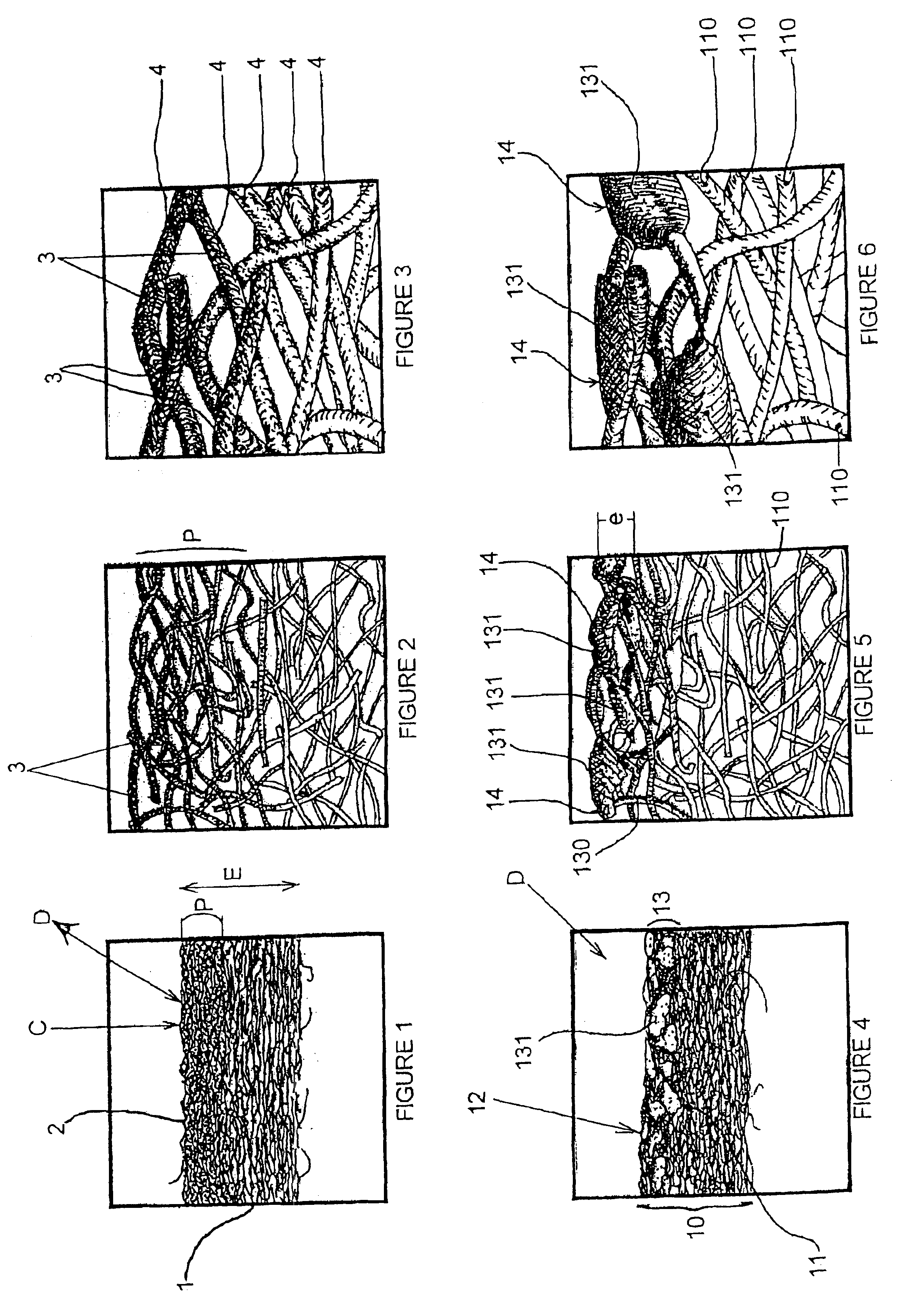
[0036]According to FIGS. 1 to 3, a known screen shown schematically in cross-section on three different scales of magnification (×20, ×80, ×350) is formed by a non-woven fabric 1 in which a decoration has been printed, from the face 2, by projection of ink jets. This projection is shown by the droplets 3 attached to the fibers 4 without however forming a film between the fibers due to the fluidity of the ink.

[0037]It will be noted that the print formed by the droplets 3 on the fibers 4 extends to a certain depth P which is substantial relative to the overall thickness E of the non woven fabric 1.

[0038]The direction of printing is shown by the arrow C. This direction of the ink jet or jets is generally perpendicular to the surface of the non-woven fabric. It can also be done at a different angle. However, due to this orientation of the ink jets and the penetration of the droplets, when it is viewed in a direction D different from the direction of printing C certain printing droplets ...


PUM

PropertyMeasurementUnit
flexibleaaaaaaaaaa
heataaaaaaaaaa
melting pointaaaaaaaaaa

Abstract

A screen formed from a stretched flexible surface, particularly for an external installation, comprises a non-woven fabric provided with a print. One face of the non-woven fabric is provided with a thin permeable layer formed by flakes which receive the print.

Description

FIELD OF THE INVENTION[0001]The present invention relates to a screen formed from a stretched flexible surface, particularly for an external installation, comprising a non-woven fabric provided with a print.BACKGROUND OF THE INVENTION[0002]A screen of the type defined above is already known and is formed by a fabric of non-woven material of which one face is provided with a print by ink jets, marking the fibers without forming a film between the fibers.[0003]Such a screen is distinguished from screens formed by canvas sheets, that is to say textile surfaces generally consisting of a polyester fabric provided with an impervious coating of polyvinyl chloride (PVC) so that it has a surface which is impermeable to air.[0004]In fact, according to certain regulations currently in force, surfaces such as canvas sheets or screens which are installed externally, in front of buildings or in isolation, must permit a certain passage of wind in order to reduce the forces exerted by the wind on t...

Claims


Application Information

Patent Timeline
Patent Type & Authority Patents(United States)
IPC IPC(8): B44D3/18D06M17/00D06P5/30D06P5/00G09F17/00G09F15/00B41J2/01B41M3/06B41M5/00D04H1/54D06C15/02D06M15/263D06M15/564G09F13/04
CPCB44D3/18D06M17/00D06P5/00G09F15/00G09F17/00D06P5/30Y10T428/2929Y10T442/159Y10T442/20Y10T442/637Y10T442/641Y10T442/699
Inventor CHENEL, GUY GILBERT
Owner CHENEL GUY GILBERT
Why Eureka
Try Eureka