Method and apparatus for reducing noise leakage from a cable modem

a cable modem and noise leakage technology, applied in the field of data transmission, can solve the problems of reducing the channel capacity of the cable system, degrading the signal quality, and not having the equipment installed for sending signals from subscribers, so as to reduce the noise leakage

Inactive Publication Date: 2005-05-03
CISCO TECH INC
View PDF12 Cites 14 Cited by
  • Summary
  • Abstract
  • Description
  • Claims
  • Application Information

AI Technical Summary

Benefits of technology

[0026]In another aspect of the invention a method of reducing noise leakage from a cable modem onto a cable plant is described. A switch component is activated when the upstream transmitter in the cable modem transmits a data signal. A data signal is then transmitted on the upstream channel. Once the data signal is transmitted, the switch component is deactivated or disabled thereby reducing noise leakage when the cable modem is not actively transmitting and terminating noise from the cable plant when the cable modem is not powered.

Problems solved by technology

However, the cable system did not have installed the equipment necessary for sending signals from subscribers to the head end, known as return or upstream signal transmission.
In addition, because cable modems were not used, the head end of pre-HFC cable systems did not contain a CMTS.
Amplifiers decrease a cable system's channel capacity, degrade the signal quality, and are susceptible to high maintenance costs.
A problem common to upstream data transmission on cable systems, i.e. transmissions from the cable modem in the home to the head end, is ingress noise at the head end which lowers the signal-to-noise ratio, also referred to as carrier-to-noise ratio.
Ingress noise can result from numerous internal and external sources.
Sources of noise internal to the cable system can include cable television network equipment, subscriber terminals (televisions, VCRs, cable modems, etc.), intermodular signals resulting from corroded cable termini, and core connections.
Significant sources of noise external to the cable system include home appliances, welding machines, automobile ignition systems, and radio broadcast.
All of these ingress noise sources enter the cable system through defects in the coaxial cable line, which acts essentially as a long antenna.
However, until that time, ingress noise is and will continue to be a problem with upstream transmissions.
In addition to ingress noise (external sources of noise to a cable plant), another source of noise on the upstream channel is transient noise leakage from a cable modem itself.
A problem occurs because control line 210 often transmits control messages from transmitter 206 to amplifier 208 at a speed that does not give the amplifier sufficient time to enable or turn on.
This can cause interference or collision of data packets during transmission.
With most variable amplifiers, the “warning” time is typically not sufficient to prepare for receiving data packets.
Consequently, data packet loss can occur.
However, it is difficult to obtain complete isolation for a cable modem.
Because control line 210 keeps the variable amplifier persistently enabled as instructed by upstream transmitter 206, there is typically a small amount of leakage at all times. While power leakage from one or two cable modems is not noticeable, a significant noise problem occurs when many modems in a service area having hundreds of cable modems, often referred to as a system of modems, have leakage.
Leakage from the modems accumulates at the head end and raises the noise floor of the upstream spectrum.
Generally, leakage from all the cable modems accumulates arithmetically to increase the noise floor of the entire upstream channel.
However, this solution is impractical and inefficient as service areas grow and the number of cable modem subscribers increases.

Method used


Image

  • Method and apparatus for reducing noise leakage from a cable modem
  • Method and apparatus for reducing noise leakage from a cable modem
  • Method and apparatus for reducing noise leakage from a cable modem

Examples


Embodiment Construction

[0037]Reference will now be made in detail to a preferred embodiment of the invention. An example of the preferred embodiment is illustrated in the accompanying drawings. While the invention will be described in conjunction with a preferred embodiment, it will be understood that it is not intended to limit the invention to one preferred embodiment. To the contrary, it is intended to cover alternatives, modifications, and equivalents as may be included within the spirit and scope of the invention as defined by the appended claims.

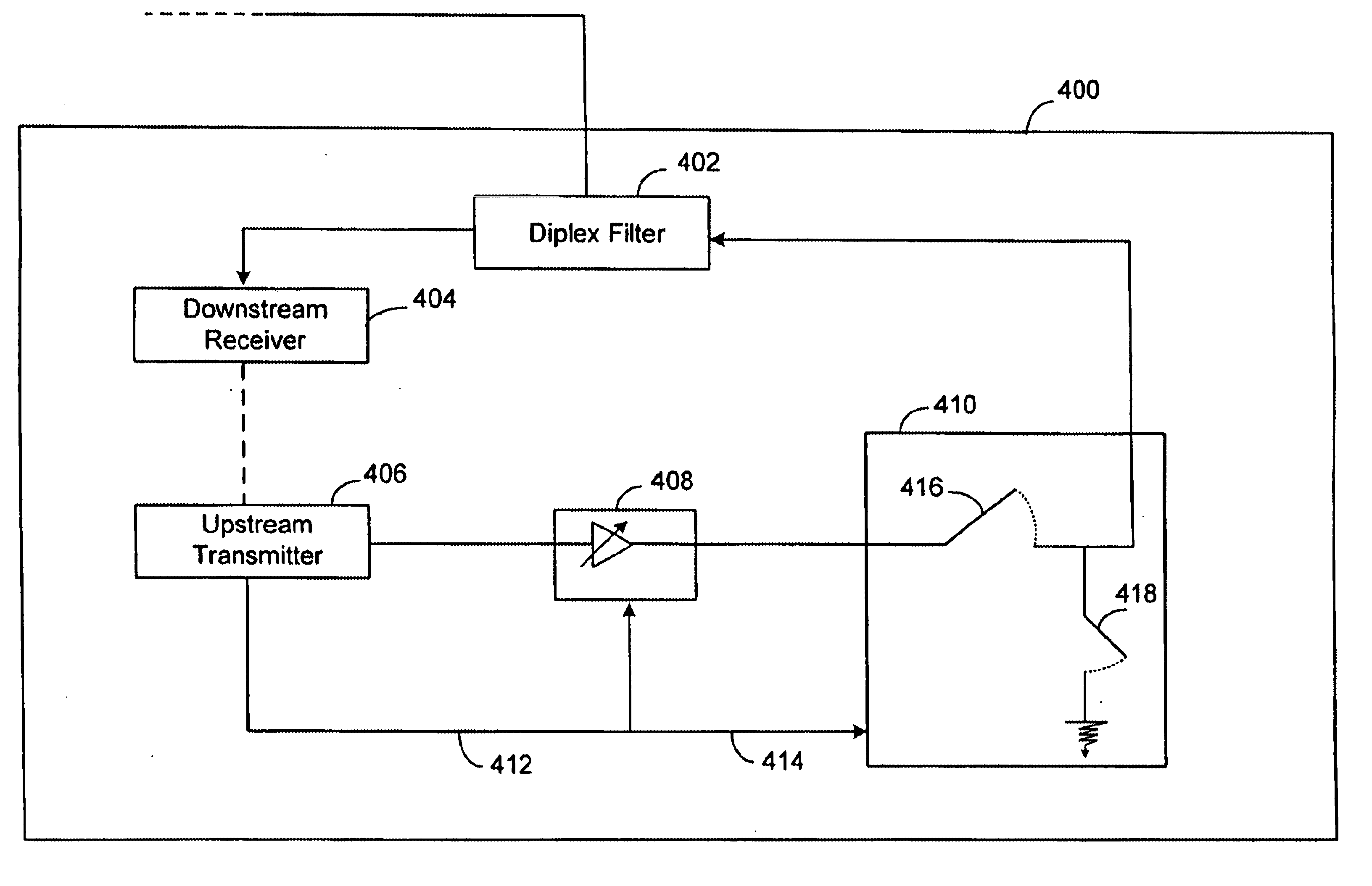
[0038]In accordance with one embodiment of the present invention, there is provided a device for reducing noise leakage from a cable modem when the cable modem is not actively transmitting and to properly terminate the cable plant when the cable modem is not in use, avoiding unwanted reflections, as described in the various figures. One way of reducing the accumulation of noise (i.e., prevent raising the noise floor) on the upstream channel for a group or sy...


PUM


Abstract

Apparatus and methods are disclosed for reducing noise leakage on the upstream channel from a cable modem. Noise leakage from cable modems, such as from a persistently enabled amplifier or other components in the modem, can accumulate on an upstream channel and reduce the overall signal-to-noise ratio of signals sent to the headend. In order to significantly reduce such noise leakage and to provide termination of the cable plant in the modem when the modem is not transmitting data, a cable modem arranged to improve its isolation is disclosed. The modem contains an upstream transmitter having a control line on which the upstream transmitter can emit a control signal. The modem also includes a switch component capable of being enabled and disabled by the control signal on the control line. The control signal from the upstream transmitter to the switch component enables the switch component thereby allowing a data signal to be transmitted on an upstream channel. The switch component includes two switches. One switch is a series switch used to enable and disable the transmission of data. Another switch is a shunt for providing termination of the cable plant. The cable modem also includes an amplifier for amplifying the data signal from the upstream transmitter before being transmitted on the upstream channel.

Description

[0001]This application is a continuation-in-part of U.S. patent application Ser. No. 09 / 344,037, filed Jun. 25, 1999 now abandoned, having Alejandro H. Schwartzman and Charles J. Naegeli as inventors, and titled METHOD AND APPARATUS FOR REDUCING NOISE LEAKAGE FROM A CABLE MODEM. This application is incorporated herein by reference in its entirety and for all purposes.BACKGROUND OF THE INVENTION[0002]1. Field of the Invention[0003]The present invention relates to transmitting data over existing cable television plants using cable modems. More specifically, it relates to reducing noise leakage from a cable modem when the modem is not transmitting data and providing matched termination to the cable plant whether or not the cable modem is active.[0004]2. Discussion of Related Art[0005]The cable TV industry has been upgrading its signal distribution and transmission infrastructure since the late 1980s. In many cable television markets, the infrastructure and topology of cable systems now...

Claims


Application Information

Patent Timeline
Patent Type & Authority Patents(United States)
IPC IPC(8): H04B1/38H04L12/28
CPCH04L12/2801
Inventor SCHWARTZMAN, ALEJANDRO H.NAEGELI, CHARLES J.
Owner CISCO TECH INC
Why Eureka
Try Eureka