
Buckle apparatus

a technology of buckle and ejector, which is applied in the direction of buckles, snap fasteners, transportation and packaging, etc., can solve the problems of inability to reliably detect the movement of latches or ejectors by magnetic sensors, and the extremely limited space inside the buckle apparatus, so as to achieve the effect of greatly and rapidly changing the electric resistance value of the giant magnetoresistive elemen

Inactive Publication Date: 2005-05-10
KK TOKAI RIKA DENKI SEISAKUSHO
View PDF13 Cites 4 Cited by
  • Summary
  • Abstract
  • Description
  • Claims
  • Application Information

AI Technical Summary

Benefits of technology

The present invention relates to a buckle apparatus for a seatbelt that includes a detection mechanism for consistently detecting when a tongue plate is inserted in a device main body. The buckle apparatus includes a latch that engages with the tongue plate and limits its movement in a disengaging direction. A giant magnetoresistive element and a permanent magnet are provided at the apparatus main body, and a shielding member interlocks with the tongue plate and moves interlockingly with it. The shielding member shields lines of magnetic force from the permanent magnet, and the movement of the tongue plate is detected by detecting changes in the electrical resistance value of the giant magnetoresistive element. The buckle apparatus can reliably detect when the tongue plate is engaged with the latch and can be used in a seatbelt system for vehicle occupants.

Problems solved by technology

However, a space in which members such as the permanent magnet and the like can move in the extremely limited space inside the buckle apparatus is extremely small.
Therefore, if mounting accuracy of the magnetic sensor and the permanent magnet is not very strict, movement of the latch or ejector cannot be reliably detected by the magnetic sensor.

Method used


Image

  • Buckle apparatus
  • Buckle apparatus
  • Buckle apparatus

Examples


Embodiment Construction

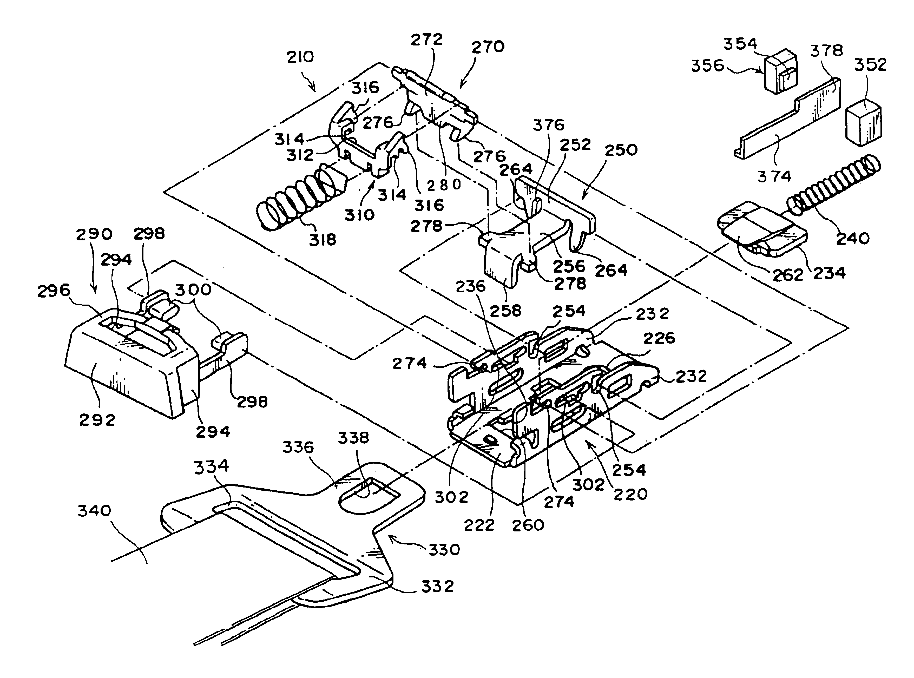
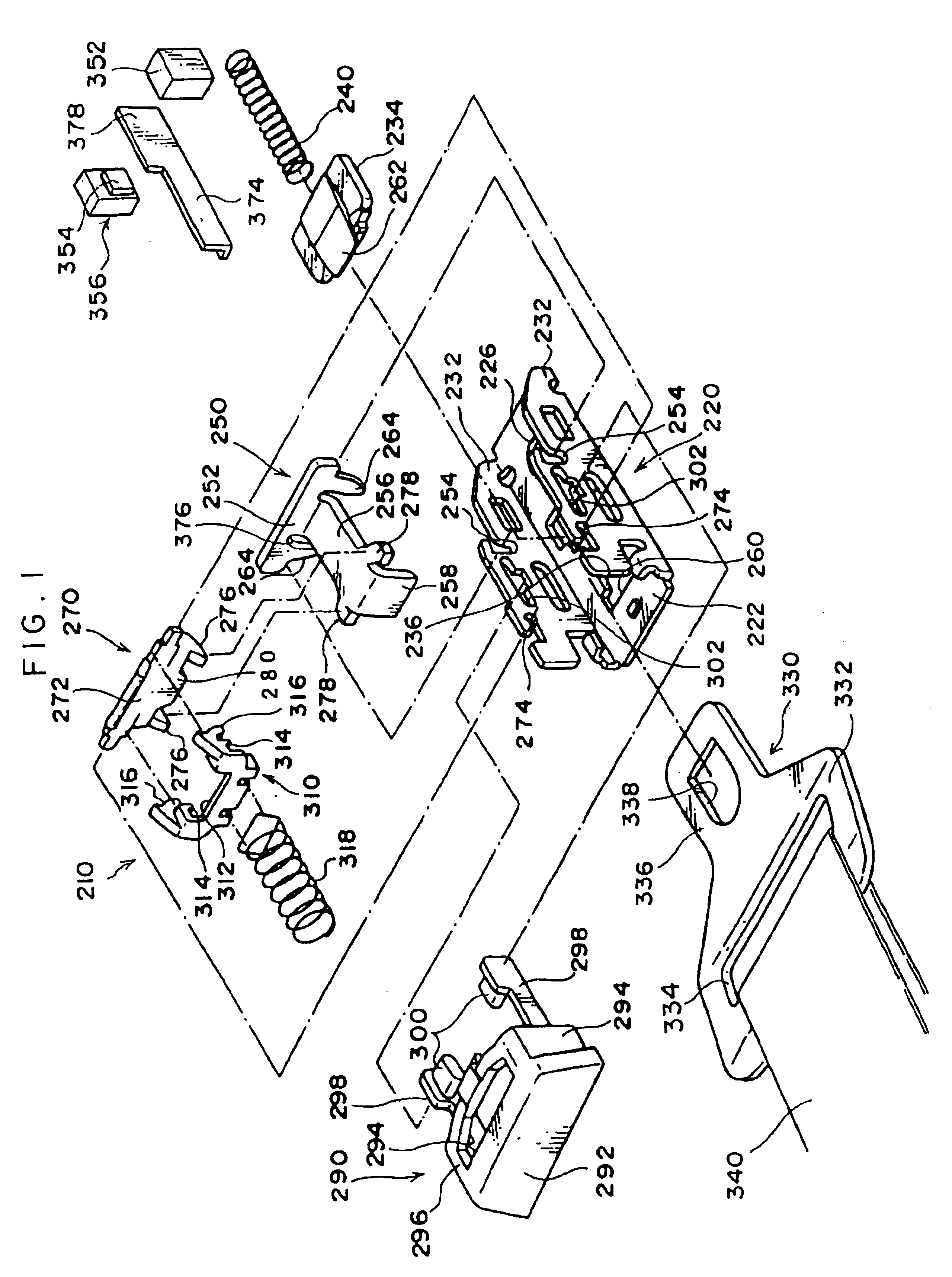
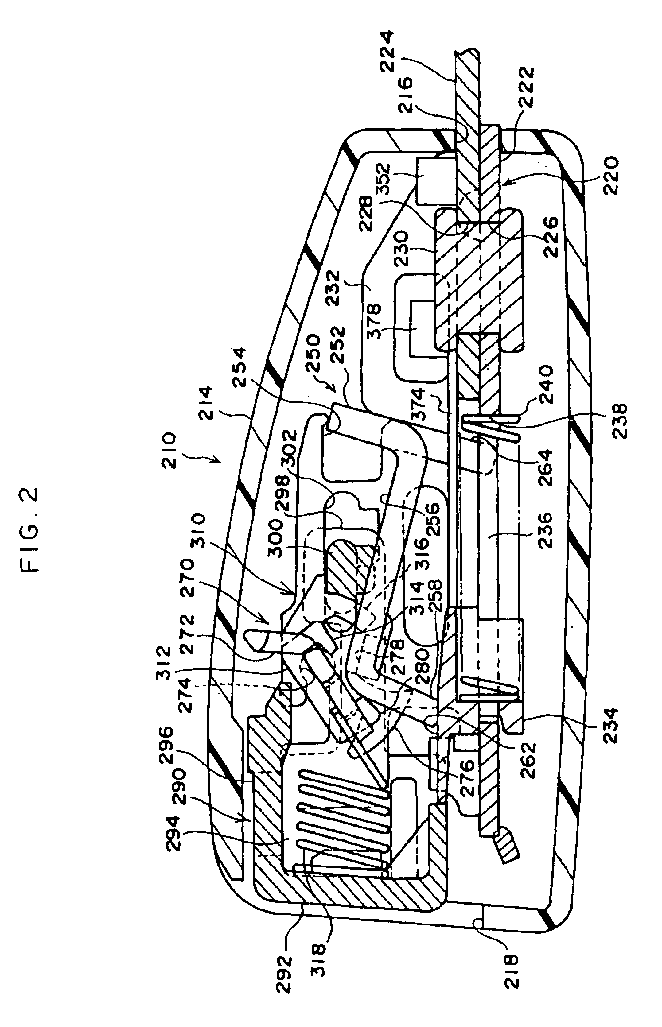
[0032]FIG. 1 shows structure of a buckle apparatus 210 relating to an embodiment of the present invention in an exploded perspective view. FIG. 2 shows the structure of the buckle apparatus 210 in a sectional view.

(Overall Structure of the Buckle Apparatus 210)

[0033]As shown in FIG. 2, the buckle apparatus 210 is provided with a case 214. The case 214 is a box-shaped tube-like member with openings formed at both ends in a longitudinal direction thereof. The opening at one end side in the longitudinal direction is an anchor insertion aperture 216. The opening at the other end side in the longitudinal direction is a tongue insertion aperture 218. A base 220 which structures the apparatus main body is accommodated inside the case 214.

[0034]As shown in FIGS. 2 and 8, the base 220 is provided with a flat plate-like baseplate 222 along the longitudinal direction of the case 214. A substantially plate-like anchor plate 224, which serves as an anchor member, is superposed at the one end sid...


PUM


Abstract

A buckle apparatus in which a permanent magnet and GMR element are provided. The polar axis of the permanent magnet is transverse to the direction a tongue plate is inserted. A shielding member is provided to an ejector of the buckle apparatus via a lever. When an inserted tongue plate of a vehicle seat belt pushes and moves the ejector as far as a position at which an engaging piece can engage with a through-hole, the shielding member is interposed between the permanent magnet and the GMR element, and the shielding member shields lines of magnetic force from the permanent magnet toward the GMR element. As a result, magnetic forces lines penetrating the GMR element are greatly reduced, and an electrical resistance value of the GMR element is suddenly and greatly changed. Thus, a buckle apparatus is provided which includes a detection mechanism that can reliably detect when the tongue plate has been inserted into the apparatus main body.

Description

BACKGROUND OF THE INVENTION[0001]1. Field of the Invention[0002]The present invention relates to a buckle apparatus for fixing a tongue plate used at a seat belt apparatus of a vehicle.[0003]2. Description of the Related Art[0004]A webbing belt structures a seat belt apparatus for restraining the body of an occupant sitting in a seat of a vehicle. One end portion in a longitudinal direction of the webbing belt is engaged with, for example, a winding shaft of a winding apparatus provided at a side of the seat. The other end portion is fixed at an anchor plate provided at a vicinity of the winding apparatus. A longitudinal direction central portion of the webbing belt passes through, for example, an insertion hole of a through-anchor provided upward of the winding apparatus, at an upper side of a center pillar of the vehicle, and is turned downward.[0005]The webbing belt, between the portion that turns down at the through-anchor and the other end, passes through an insertion hole of a...

Claims


Application Information

Patent Timeline
Patent Type & Authority Patents(United States)
IPC IPC(8): B60R22/00B60R22/48A44B11/25
CPCB60R22/48Y10T24/32Y10T24/45623B60R2022/4816
Inventor ITOIGAWA, KOUICHIMURAKI, HITOSHI
Owner KK TOKAI RIKA DENKI SEISAKUSHO
Learn More