Flow metering

a flow meter and flow meter technology, applied in the field of flow metering, can solve the problems of inability to reliably calibrate flow meter, inability to precisely know the operational environment in which the meter is to be fitted, and inability to accurately pre-calibrate flow meter, etc., to improve the accuracy of factory calibration of flow meter and improve the accuracy of meter output.

Inactive Publication Date: 2005-05-10
EHNDRESS KHAUZER GMBKH KO KG
View PDF10 Cites 12 Cited by
  • Summary
  • Abstract
  • Description
  • Claims
  • Application Information

AI Technical Summary

Benefits of technology

[0007]Thus, regardless of the internal diameter or condition of the upstream pipeline, the adapter extension provides the flow meter with known upstream conditions. The internal surface of the pipeline immediately upstream of the flow meter is masked by the adapter extension. In addition, the adapter extension prevents any gasket used to seal the flow meter to the pipeline flange from protruding into the flow passageway immediately upstream of the meter.
[0008]The tubular extension may itself be mounted on a flange which in use is inserted between a flange of the flow meter and the pipeline flange. A factory-defined seal may be provided between the flow meter and the adapter flange, obviating the need to provide a gasket of unpredictable configuration between the installation adapter and the flow meter.
[0009]A meter installation adapter as defined above does make it possible to predetermine conditions immediately upstream of a flow meter and thereby to improve the accuracy of factory calibration of a flow meter. The conditions in which the flow meter is used can however change in an unpredictable manner as a result of other factors, for example instability in the flow resulting from upstream bends and discontinuities in the pipeline, particularly when flow rates vary to a substantial extent. For example, if a thermal loss flow meter provided with a single thermal loss sensor is calibrated on the basis that a fully developed flow is expected in the vicinity of the sensor, and yet conditions change such that the fully developed flow is disrupted, the relationship between the sensor output and the flow may be radically altered, rendering the meter output inaccurate. If a single sensor is positioned at three quarters of the radius of the pipeline away from the pipeline axis in a position which can be represented at 12 o'clock, the same sensor located at the same distance from the pipeline axis at a position which could be represented as for example 3 o'clock could produce a very different output if the flow meter is positioned downstream of a disturbance creator such as a single bend in one plane or more complex bend combinations. Where a flow meter is positioned other than in a fully developed flow a change in flow rate can in effect cause a rotation in the flow conditions in the vicinity of the flow meter. A flow meter calibrated in one set of conditions therefore may provide inaccurate data if those conditions change.

Problems solved by technology

Each type of known flow meter has its advantages and disadvantages but with many flow meters and in particular thermal loss flow meters it is difficult to pre-calibrate a meter without a precise knowledge of the operational environment in which that meter is to be fitted.
One problem encountered when installing flow meters is that such meters are generally inserted between flanges of a pipeline.
Even if for a particular installation the nominal internal diameter of a pipe upstream of the intended meter location is known, there is almost inevitably a discontinuity as between the meter body inlet and the pipe immediately upstream of that inlet which generates unpredictable effects within the meter body.
Such unpredictable effects make it impossible reliably to calibrate a flow meter until that flow meter has been installed in its final place of use.

Method used


Image

  • Flow metering
  • Flow metering
  • Flow metering

Examples


Embodiment Construction

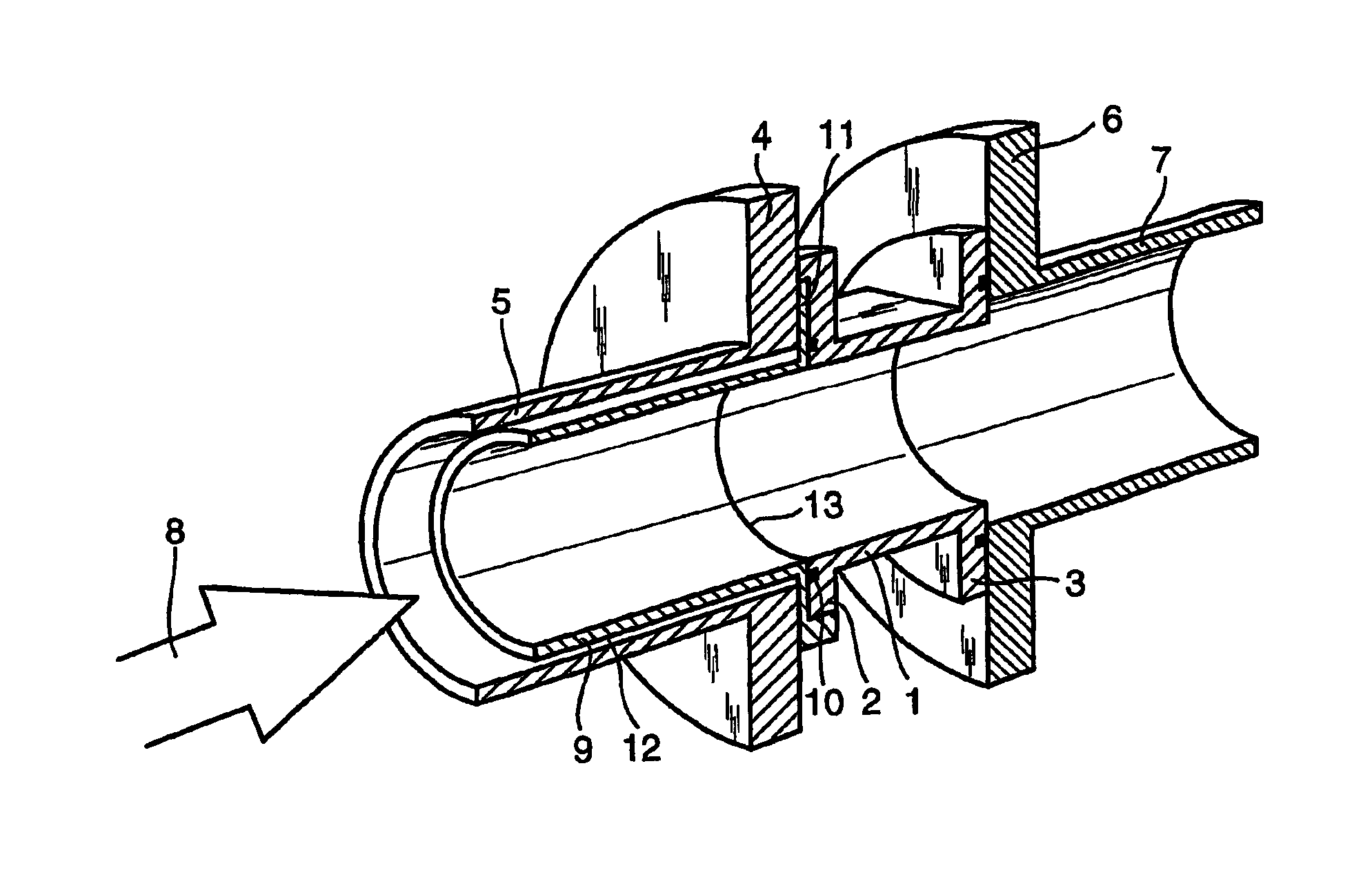
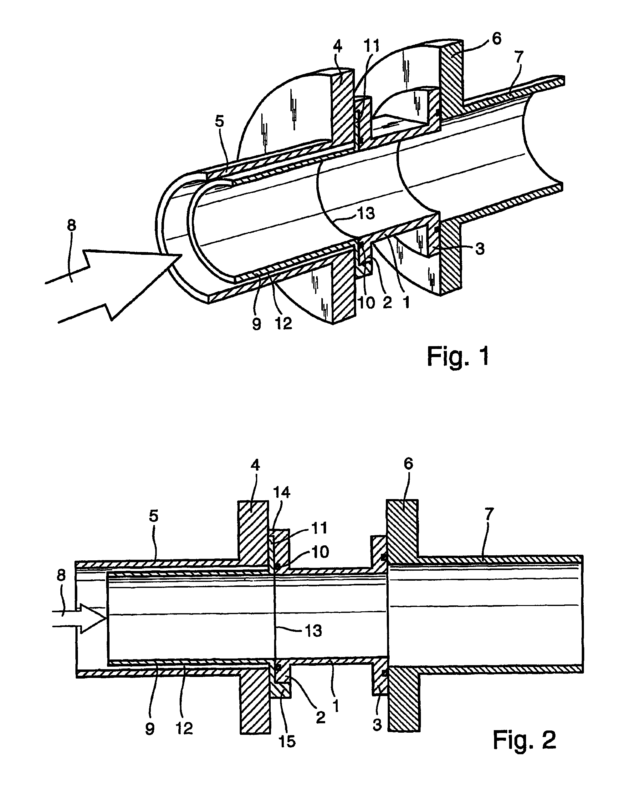
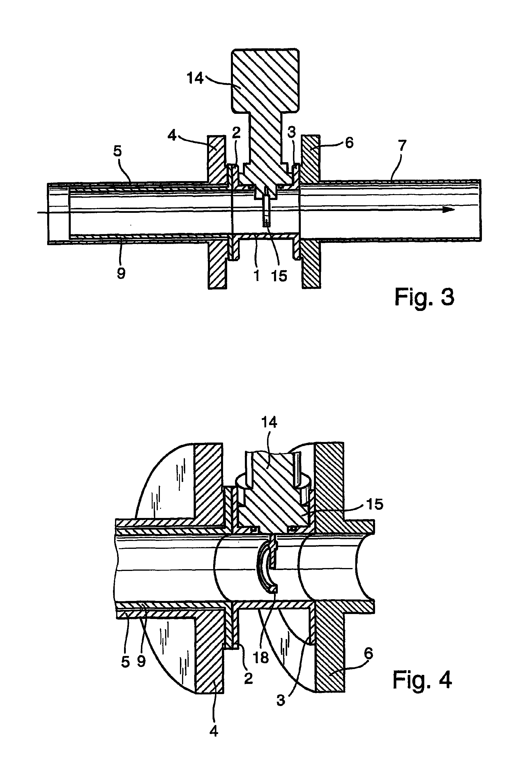
[0031]Referring to FIGS. 1 and 2, the illustrated assembly comprises a flow meter body 1 defining flanges 2 and 3 sandwiched between a flange 4 mounted on one end of a pipeline 5 and a flange 6 mounted on one end of a pipeline 7. In use, a flow meter sensor (not shown) is supported in the flow meter body 1 so as to be exposed to fluid flowing in the direction of arrow 8 through the assembly. A meter installation adapter 9 extends into the upstream pipe 5 from the body 1. The adapter is sealed to the meter flange 2 by an O-ring 10 that seats against a flange 11 on the downstream end of the adapter 9. The outside diameter of the adapter 9 is less than the inside diameter of the pipe section 5 such that an annular space 12 is defined outside the adapter 9. The inside diameter of the adapter 9 is the same as the inside diameter of the meter housing 1 and the flanges 2 and 11 are dimensioned such that the axes of the body 1 and adapter 9 are in alignment. Thus there is no surface discont...


PUM


Abstract

A flow meter incorporating thermal loss sensors and an installation adapter to provide known flow conditions upstream of the meter. The installation adapter is in the form of a tubular extension projecting from a flange which in use is sandwiched between a pipeline flange and a flow meter flange. The flanges are configured such that a passageway defined by the adapter extension is located in a predetermined position relative to the flow meter. The flow meter may comprise a sensor array supporting at least three sensors which are not in alignment, one of those sensors being located centrally within the flow meter and the others being distributed at equal distances around the central position. In use, normal readings may be taken from a single one of the sensors, the other sensors being used for initial calibration and subsequent calibration test purposes only. A comparison is made between the relative values of the outputs of the different sensors to identify sensor drift or potentially significant changes in flow conditions.

Description

[0001]This application is a 371 of PCT / EPO02 / 04637 Apr. 26, 2002.FIELD OF THE INVENTION[0002]The present invention relates to flow metering, and in particular to a flow meter installation adapter, a flow sensor array, and a method for operating a multi-sensor thermal loss flow meter.BACKGROUND OF THE INVENTION[0003]Flow meters are well known devices that can be used to measure the rate of flow of a fluid such as a liquid or gas through a pipe. Known flow meters monitor various conditions such as the rate of loss of heat from a heated sensor or differential pressures to provide an output representative of flow conditions within the body of a flow meter. Each type of known flow meter has its advantages and disadvantages but with many flow meters and in particular thermal loss flow meters it is difficult to pre-calibrate a meter without a precise knowledge of the operational environment in which that meter is to be fitted. As a result, it is often the case that flow meters are delivere...

Claims


Application Information

Patent Timeline
Patent Type & Authority Patents(United States)
IPC IPC(8): G01F1/696G01F1/684G01F1/69G01F15/18G01F25/00G01F15/00G01F1/68G01F1/00
CPCG01F1/6842G01F1/69G01F25/0007G01F15/185G01F1/6965G01N21/05G01F25/10
Inventor GIMSON, CHRIS
Owner EHNDRESS KHAUZER GMBKH KO KG
Why Eureka
Try Eureka