Peak flow meter

a peak flow and meter technology, applied in the field of spirometry, can solve the problems of difficult zero of meters, cumbersome transportation of meters, and inability to be commercialized, and achieve the effect of meaningful results, high accuracy, and sufficient accuracy and repeatability

Inactive Publication Date: 2005-05-10
NEWVED
View PDF5 Cites 13 Cited by
  • Summary
  • Abstract
  • Description
  • Claims
  • Application Information

AI Technical Summary

Benefits of technology

[0017]It is a further aspect of the invention to provide a peak flow meter that is sufficiently accurate and repeatable to provide meaningful results.
[0018]It is a further aspect of the invention to provide a peak flow meter that does not require a customized scale to provide the necessary level of accuracy.
[0019]It is a further aspect of the invention to provide a peak flow meter that is not prone to corruption of test results through blockage of the air outlet or flow restrictor by a user's finger.
[0020]It is a further aspect of the invention to provide a peak flow meter that may be manufactured and sold at a relatively low cost.

Problems solved by technology

A wide variety of peak flow meters are commercially available and many more have been patented, but not commercialized.
Although these flow meters are relatively popular, they have a number of drawbacks.
First, in order to obtain an acceptable level accuracy, a relatively long spring and housing must be utilized, making the meter cumbersome to transport.
Second, the arrangement of the spring, and variations in effective lengths due to manufacturing tolerances, makes these meters difficult to zero.
Accordingly, these meters require the use of springs with extremely tight manufacturing tolerances.
Third, the location of the air outlet at the end of the meter makes them prone to blockage or influence by the fingers of the user, resulting in corruption of test results.
Finally, the location of the air restrictor within the air outlet makes them prone to blockage or influence as well, again resulting in corruption of test results.
However, they are also generally too large to be truly portable and are much more expensive than non-electronic versions.
Further, these units will not operate without properly charged batteries, creating the risk that user will not detect the onset of an asthmatic attack when the batteries are low or completely depleted.
A vane assembly is rotatably attached to a torsion spring and is dimensioned such that it interferes with the indicator when it is rotated.
However, conventional rotary peak flow meters are not without drawbacks.
Given the tolerances inherent in the process of manufacturing the torsion springs, the variation in this positioning can result in significant inaccuracies.
However, this process requires that each unit be tested to generate the values for this custom scale, causing a corresponding increase in cost.
As was the case with these meters, this outlet is prone to blockage by the finger of the user, resulting in corruption of test results.
Finally, the location of the air flow restriction within the air inlet makes them prone to the same corruption as their linear counterparts.

Method used


Image

  • Peak flow meter
  • Peak flow meter
  • Peak flow meter

Examples


Embodiment Construction

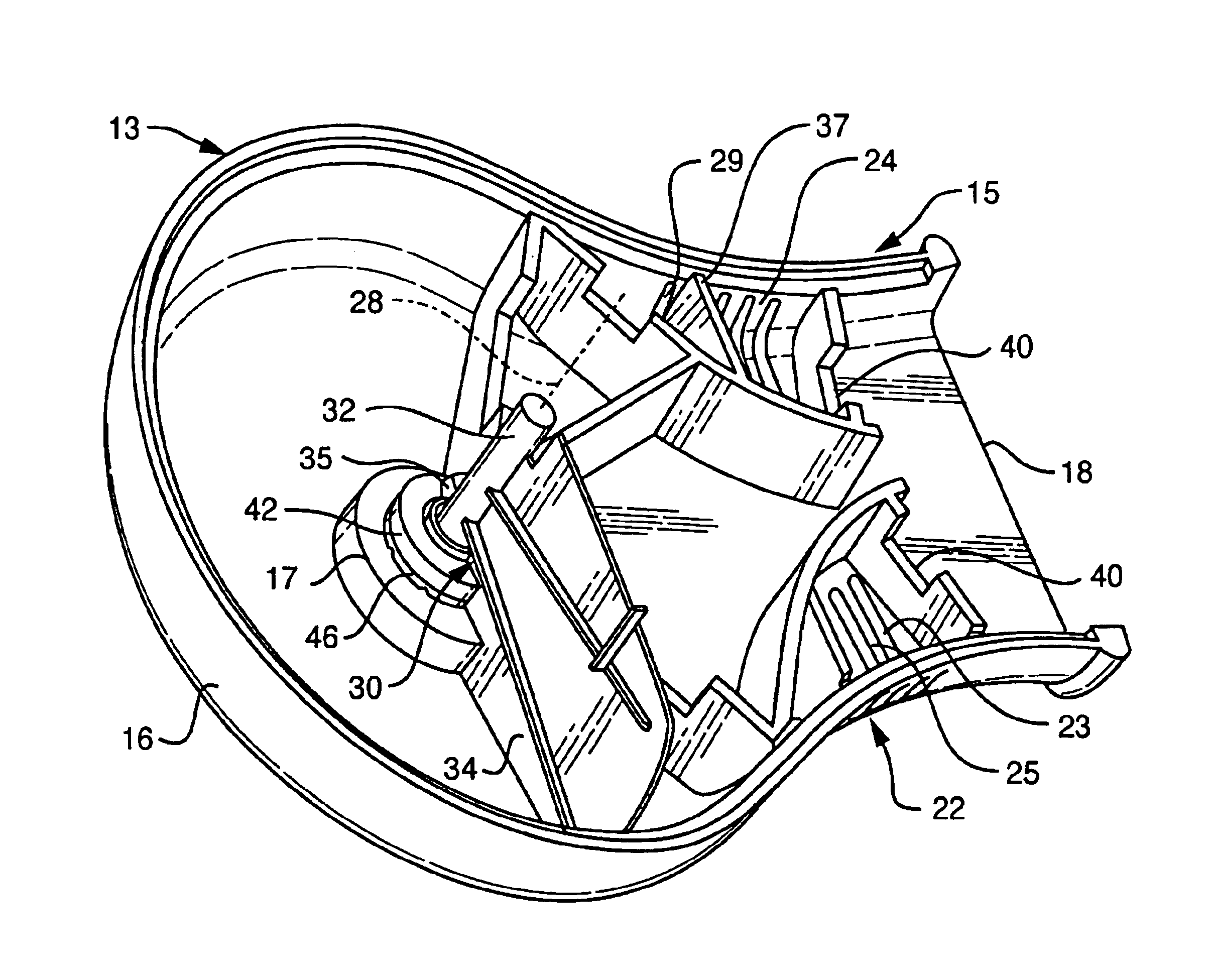
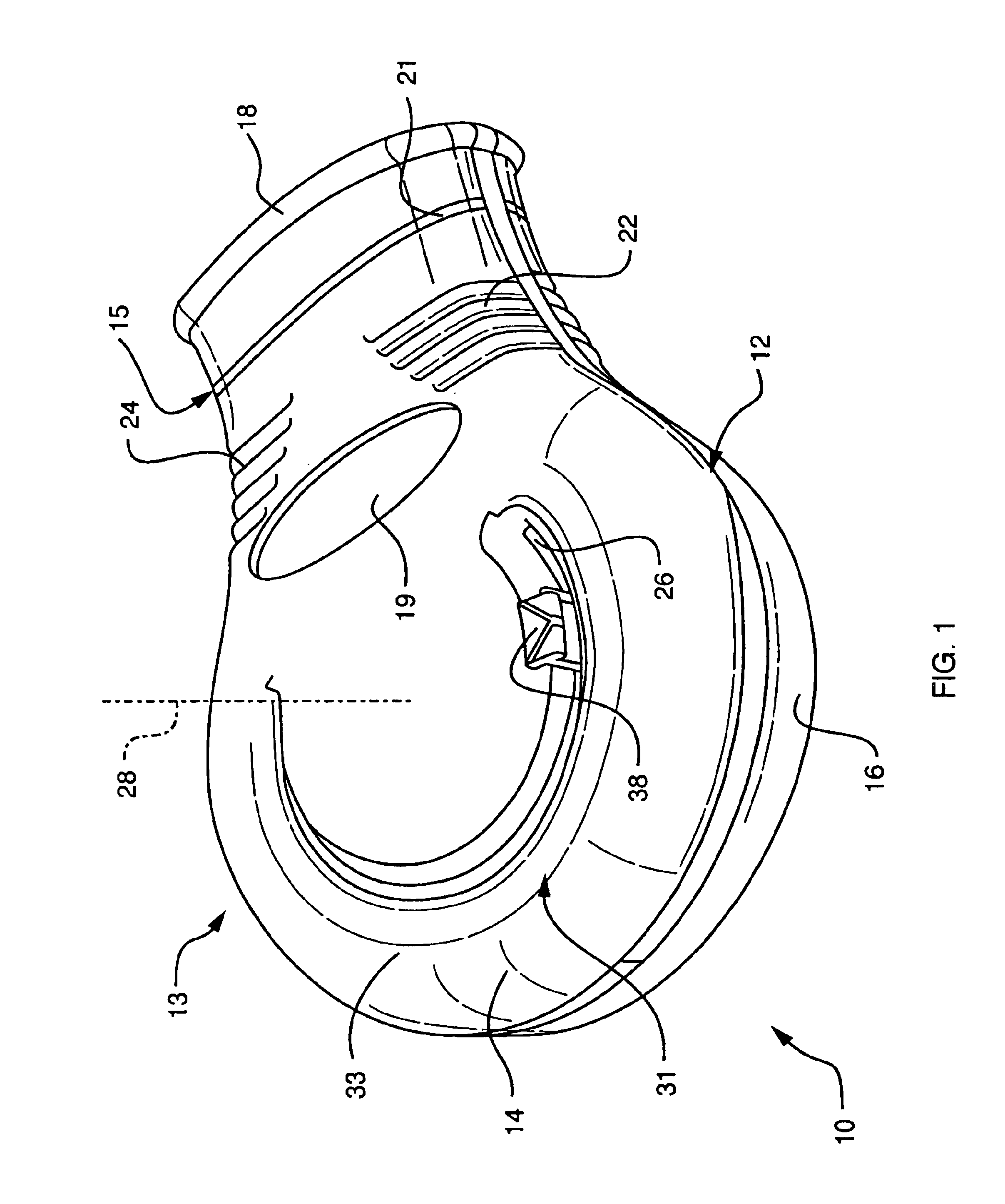
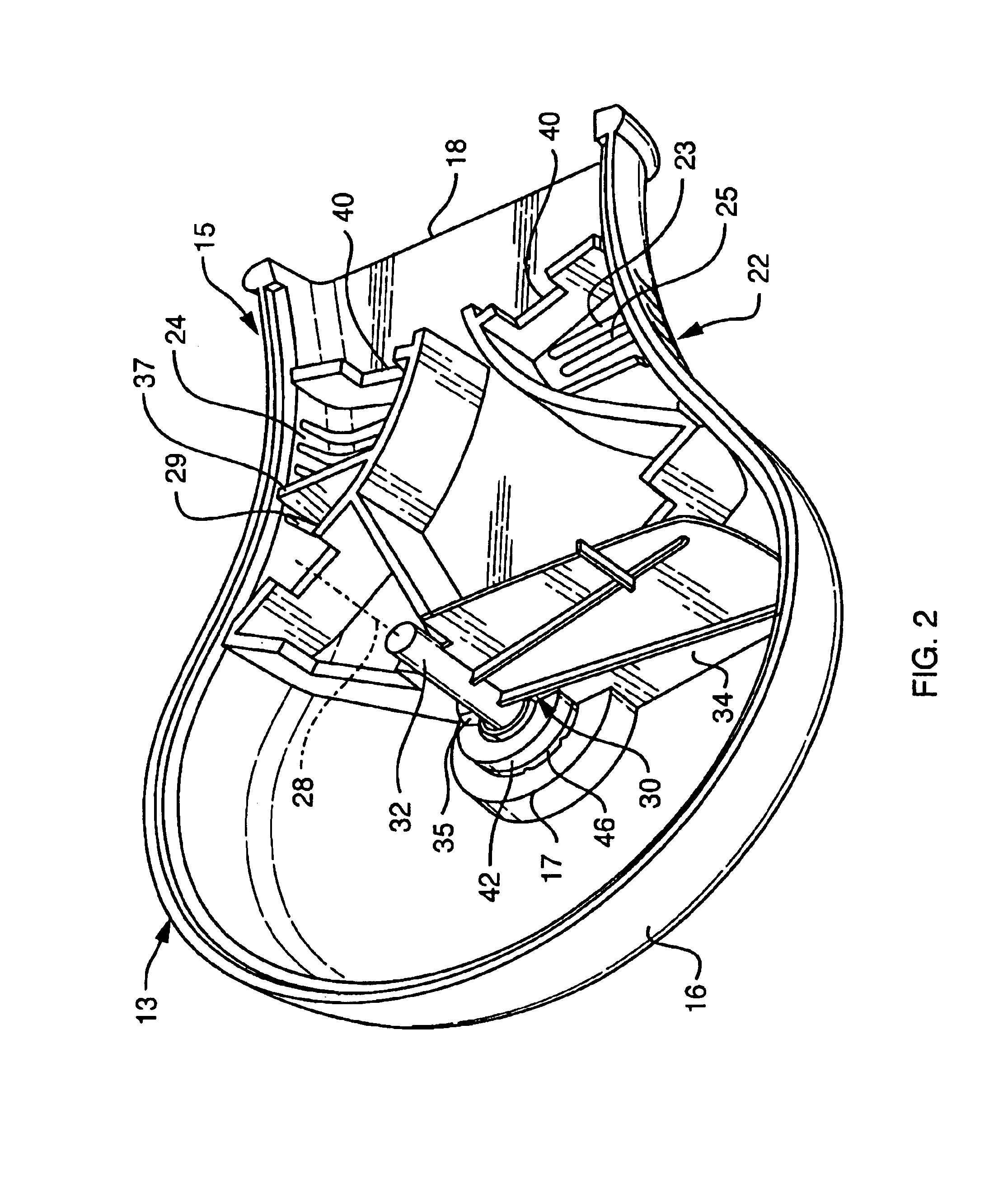
[0030]Referring first to FIGS. 1 and 2, one embodiment of the preferred peak flow meter 10 of the present invention is shown. In the embodiment of FIGS. 1 and 2, the peak flow meter 10 includes a substantially hollow housing 12 having a top portion 14, a bottom portion 16, an air inlet 18 and two air outlets 22, 24. A vane assembly 30 is disposed within the housing 12 and includes a vane 34, a post 32 to which the vane 34 is attached, a hub 42 that is attached to the bottom portion 16 of the housing 14. A torsion spring (shown in FIG. 4) that is disposed between the hub 42 and the post 32, and a mechanical indicator 38 is provided for indicating a peak flow of air into the meter 10.

[0031]The housing 12 preferably includes a disc-like measurement portion 13 and an elliptical flow portion 15 that includes the air inlet 18 and the two air outlets 22, 24. In the preferred embodiment, finger pads 19 are provided on the top portion 14 and bottom portion 16 of the housing 12 in order to re...


PUM


Abstract

A peak flow meter for measuring a peak flow or air exhaled by a patient. The preferred peak flow meter includes a substantially hollow housing having a top portion, a bottom portion, an air inlet and at two air outlets. A flow restriction is disposed within the housing and in fluid communication with the air inlet. A vane assembly is disposed within the housing and includes a vane, a post to which the vane is fixedly attached, and a hub attached to the bottom portion of the housing. A torsion spring is engaged at one end to the hub and at the other to the post A visual indictor is movably disposed within the slot for indicating a peak flow rate of air based upon a movement of the vane and a scale is disposed proximate to the slot such that the location of the visual indicator may be related to a corresponding flow rate.

Description

FIELD OF THE INVENTION[0001]The present invention relates to the field of spirometry and, in particular, to a portable peak flow meter and kit for measuring the peak flow of air exhaled by a user.BACKGROUND OF THE INVENTION[0002]Asthma is a disease that effects about 4% of the population of the United States or about 15 million people. The incidence of asthma has grown at an alarming rate, up nearly 75% in the past decade. It is a very complex disease, having multiple etiologies involving inflammatory cells, mediators, and the cells and tissues that line airways. Symptoms are many and varied including wheezing, shortness of breath, chest tightness and cough. Several classes of medications have been developed to combat asthma such as beta agonists, anti-inflammatory and anti leukotrienes. Aggressive management plans have been designed that include medication, monitoring and lifestyle adjustments to maintain patients at optimal levels of health.[0003]The diagnosis of asthma includes a...

Claims


Application Information

Patent Timeline
Patent Type & Authority Patents(United States)
IPC IPC(8): G01F1/20G01F1/28
CPCG01F1/28
Inventor MARCOTTE, RONALD P.MANCHESTER, WALTERHENTON, DONALDPARENT, DONALDGEHAN, TULLY
Owner NEWVED
Why Eureka
Try Eureka