Combined shut-off valve and cover for an engine breather system

a technology of engine shut-off valve and cover, which is applied in the direction of machines/engines, mechanical equipment, engine components, etc., can solve the problems of substantial quantities of oil flowing under gravity and entering the engine induction system, and oil may not return to the sump

Inactive Publication Date: 2005-05-10
PERKINS ENGINES
View PDF11 Cites 19 Cited by
  • Summary
  • Abstract
  • Description
  • Claims
  • Application Information

AI Technical Summary

Problems solved by technology

Under abnormal operating conditions, such as sump overfill or excessive blow-by of oil arising from a worn engine, there is a risk that oil may not return to the sump, but may be directed to the pressure regulation valve and hence to the engine induction system by gravity, resulting in undesirable engine emissions.
If the engine is mounted in a vehicle or machine that is operated at an extreme inclination or rolls over, there is a risk that substantial quantities of oil can flow under gravity and enter the engine induction system.
This can cause the engine to run in an ungoverned condition and can result in damage to the engine as well as undesirable engine emissions.

Method used


Image

  • Combined shut-off valve and cover for an engine breather system
  • Combined shut-off valve and cover for an engine breather system
  • Combined shut-off valve and cover for an engine breather system

Examples


Embodiment Construction

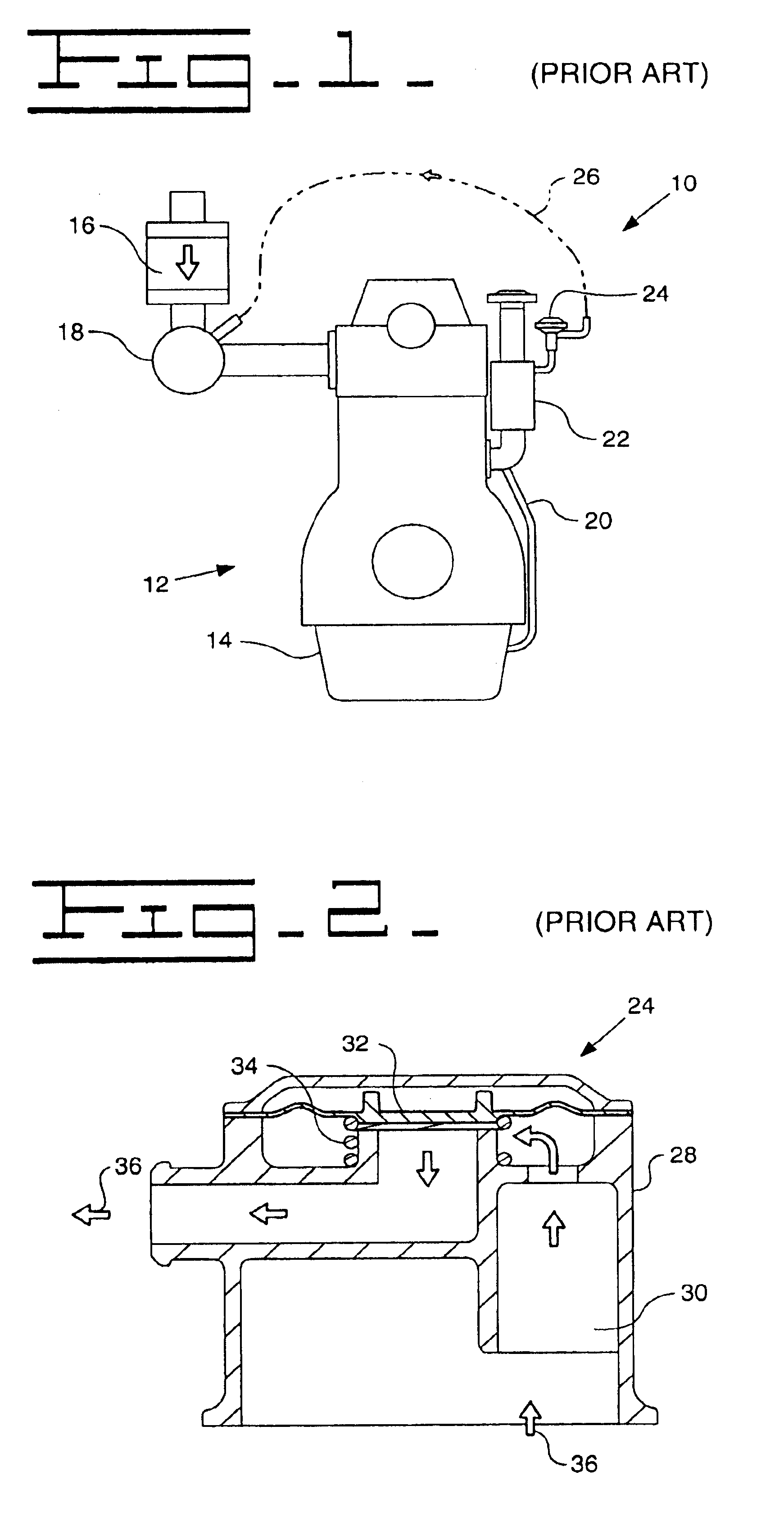
[0015]A known closed breather system 10 is shown in FIGS. 1 and 2. An engine 12 has a crankcase 14, an air filter 16 and an induction manifold 18. Blow-by gas which escapes past the pistons (not shown) into the crankcase 14 mixes with airborne oil droplets in the crankcase and is fed back to the engine induction system. The gas first passes through the crankcase breather pipe 20 to a combined filter / separator 22 that separates the oil from the blow-by gas before allowing the oil to return to the crankcase 14 under gravity. The blow-by gas then continues through a pressure regulation valve 24 and along an air intake pipe 26 to the induction manifold 18. The closed breather system shown in FIG. 1 does not include a shut-off valve.

[0016]The pressure regulation valve 24 is shown in more detail in FIG. 2 and has a housing 28 with a crankcase inlet 30 connected to the crankcase breather pipe 20 via the combined filter / separator 22 and an induction manifold outlet connected to the air inta...


PUM


Abstract

In prior art engine breather systems, shut off valves that prevent oil from entering the engine induction system have been mounted externally on the engine and require associated external pipework. Both the shut off valve and pipework are prone to damage and leaking. The closed circuit breather apparatus of the present invention includes a cylinder head cover and a shut off valve provided beneath the cylinder head cover. The shut off valve includes an aperture in communication with a blow-by gas inlet passage and a valve float restrained to move between a first position in which the aperture is open and a second position in which the aperture is closed. Preferably the shut off valve is integral with the cylinder head cover. The shut off valve is thus packaged inside the engine valve chamber, making it easy to fit and eliminating leak paths.

Description

TECHNICAL FIELD[0001]This invention relates to breather systems in internal combustion engines which allow the free flow of bypass gases and air movement between chambers of the engine during engine running, and to shut-off valves provided in such breather systems to prevent oil in the breather system from entering the engine induction system, and is particularly but not exclusively applicable to closed circuit breather systems.BACKGROUND[0002]An internal combustion engine typically has three chambers, the crankcase, the timing case and the top cover. Each of these chambers must be openly connected to allow free flow of bypass gases and air movement during engine running. In a closed breather system blow-by gas escapes past the piston into the crankcase where it mixes with airborne oil droplets and is fed back into the engine induction system. The blow-by gas passes through a woven mesh oil separator that separates the oil from the blow-by gas before allowing the oil to return to th...

Claims


Application Information

Patent Timeline
Patent Type & Authority Patents(United States)
IPC IPC(8): F01M13/04F01M13/00
CPCF01M13/0416F01M2013/0016
Inventor PATEMAN, RICHARDBEDKOWSKI, MACIEJ
Owner PERKINS ENGINES
Why Eureka
Try Eureka