High efficiency isothermal heat sink

a heat sink and high efficiency technology, applied in the field of heat sinks, can solve the problems of small power to drive the chips comprising chips, heat generated in the integrated circuit, and rapid increase in heat when the ics operate, and achieve the effect of improving the efficiency of cooling electronic instruments and high efficiency

Inactive Publication Date: 2005-05-10
EPOS LTD
View PDF10 Cites 92 Cited by
  • Summary
  • Abstract
  • Description
  • Claims
  • Application Information

AI Technical Summary

Benefits of technology

[0012]The main objective of the invention is to provide a high efficiency heat sink to quickly dissipate heat from a heat source.
[0013]A high efficiency isothermal heat sink in accordance with the present invention includes a plate body. The body has a top and includes a housing, an interior partition and a wick. The housing has an inner chamber under a vacuum and includes a cover and a base. The interior partition is mounted between the cover and the base to divide the inner chamber into an upper half chamber and a lower half chamber and has a central through hole and multiple air passages to allow the lower half chamber and the upper half chamber to communicate. The wick contains a working fluid, is mounted and held in the central through hole in the interior partition and has a lower evaporating section and an upper condensing section. The lower evaporating and the upper condensing sections are respectively held in the lower and the upper half chambers. Therefore, the working fluid in the lower evaporating section is evaporated to produce a vapor that flows into the upper half chamber through the air passages in the interior partition from the lower half chamber. In the upper half chamber, the vapor condenses into liquid in the condensing section where the working fluid in the condensing section returns to the evaporating section to provide an improved efficiency of cooling electronic instruments.

Problems solved by technology

Although power to drive the ICs comprising chips is very small, heat is generated when the integrated circuits operate.
In high performance integrated circuits, such as central processing units (CPU) or video integrated circuits for computers, heat rapidly increases when the ICs operate.
However, the vapor and the returning working fluid in the wick (61) are in the same inner chamber (601), which causes a low efficiency of heat exchange in the inner chamber (601) for the conventional heat sink.
The deformed top and bottom of the body (60) cannot efficiently contact with the heat source (80) and the fins (70), which further lowers the efficiency of the heat sink.

Method used


Image

  • High efficiency isothermal heat sink
  • High efficiency isothermal heat sink
  • High efficiency isothermal heat sink

Examples


Embodiment Construction

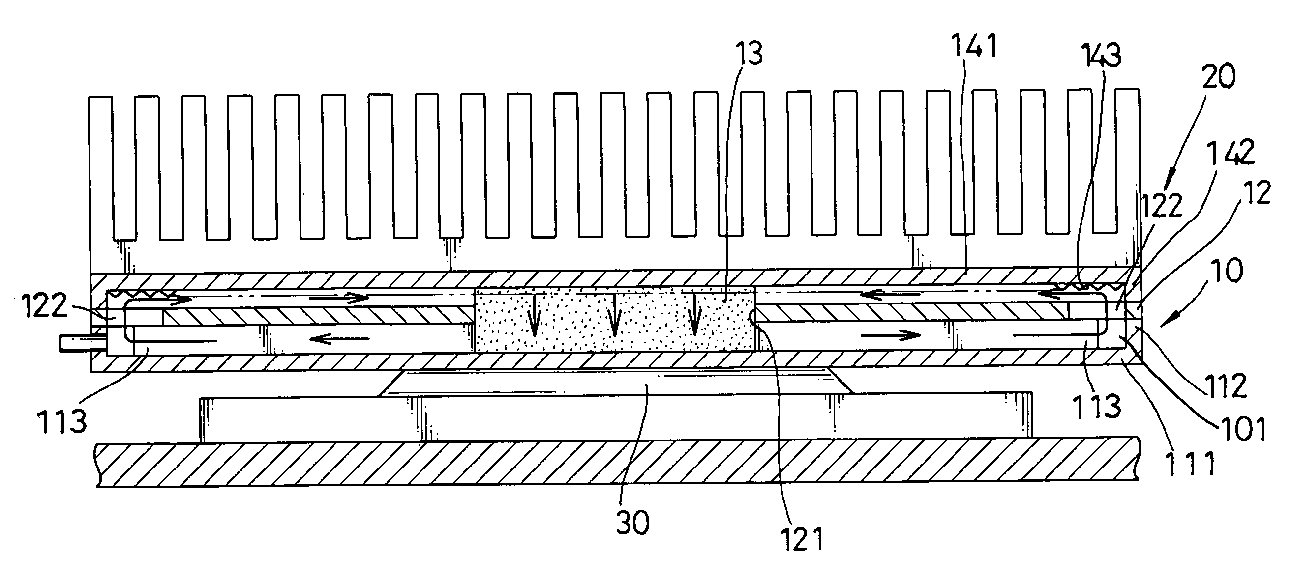
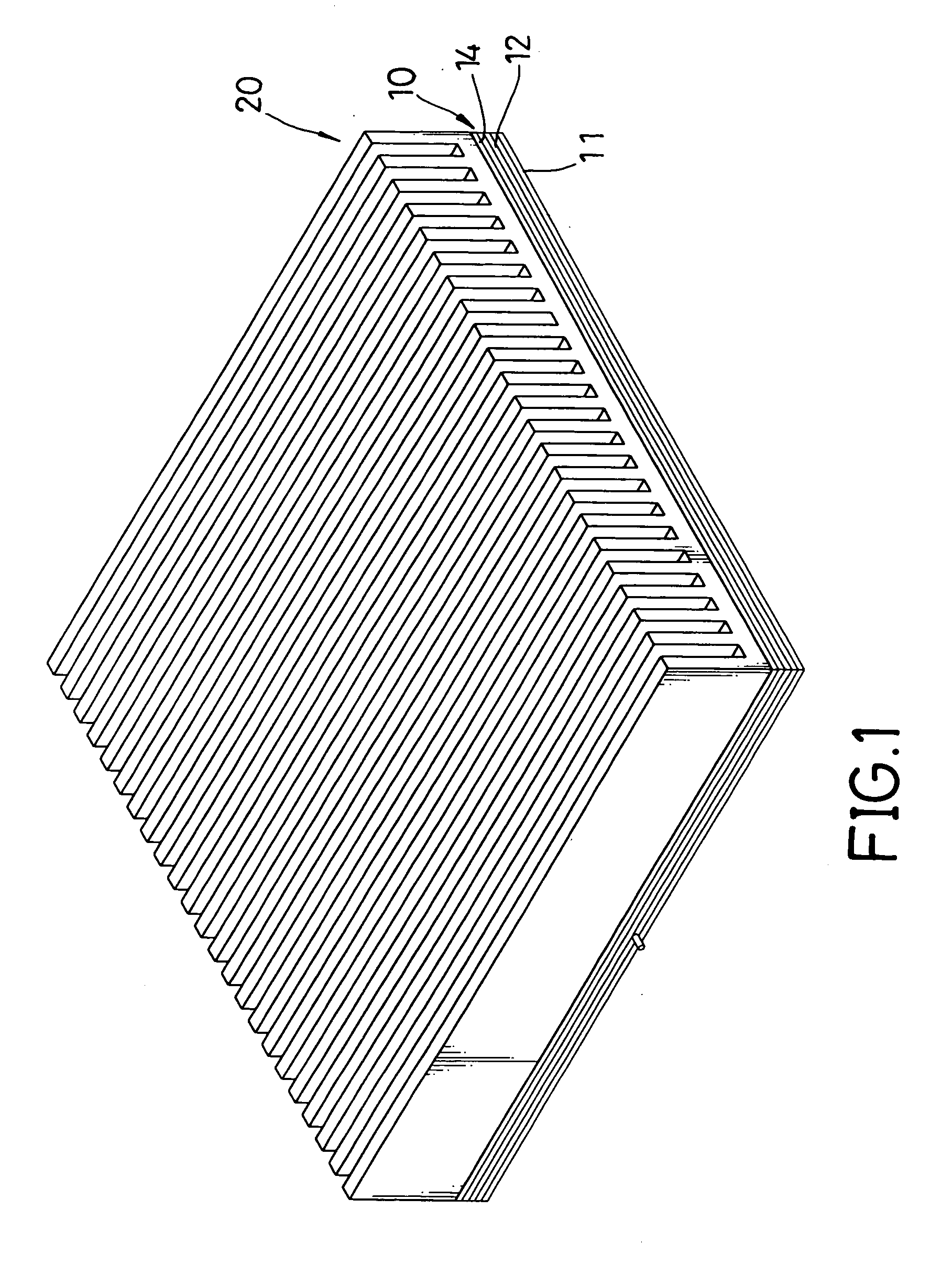
[0019]With reference to FIGS. 1 and 2, a high efficiency isothermal heat sink in accordance with the present invention uses the operational principles of heat pipes and comprises a plate-like body (10) and external fins (20).

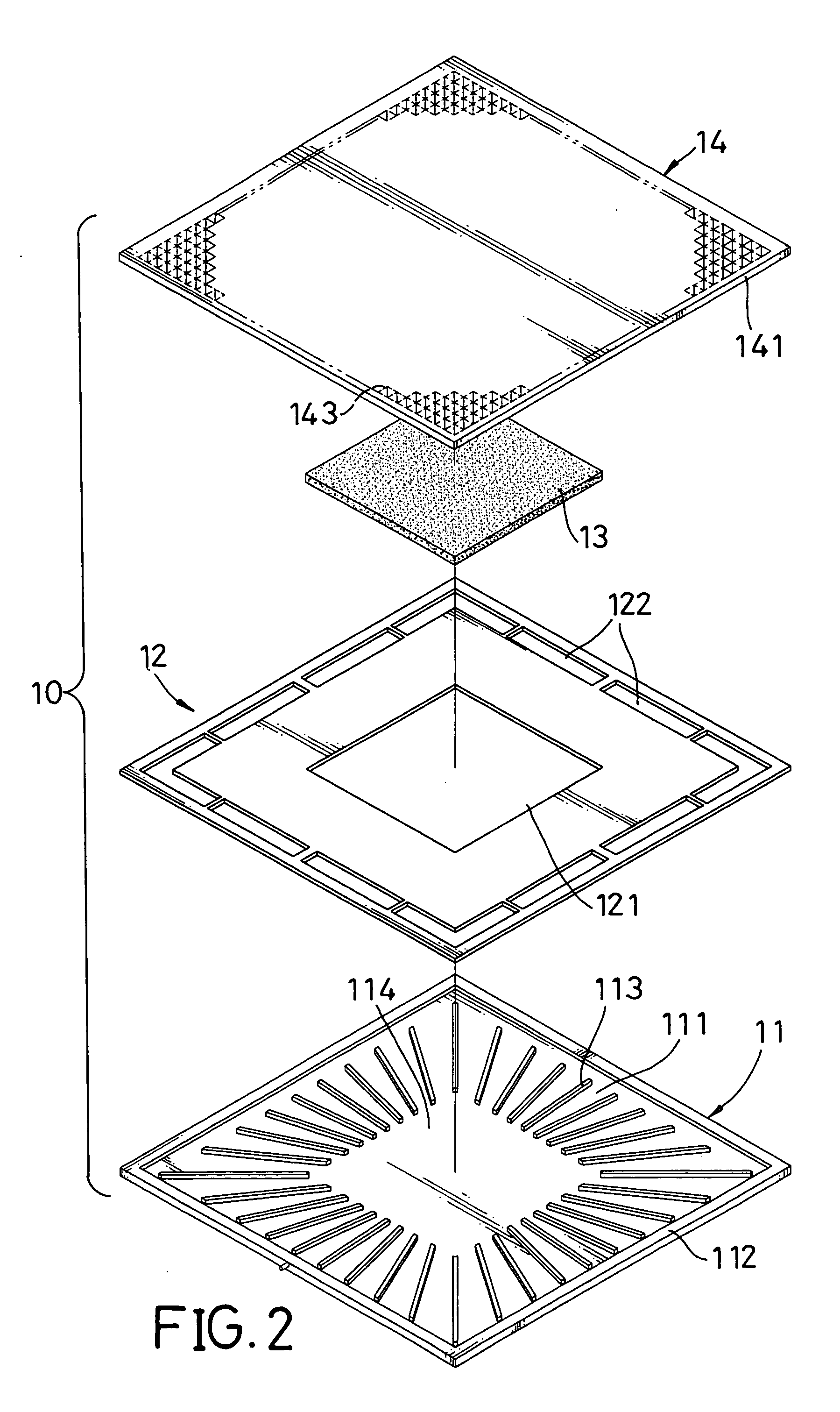
[0020]With further reference to FIG. 3, the body (10) is hollow, has a top (not numbered), a bottom (not numbered) and comprises a housing (not numbered), a wick (13) and an interior partition (12). The housing has an inner chamber (101), may be made of metal and comprises a cover (14) and a base (11). The inner chamber (101) is maintained in a vacuum. The cover (14) comprises an upper substrate (141) and an upper flange (142). The upper substrate (141) and has a bottom (not numbered), an outer edge (not numbered) and multiple grooves (143). The grooves (143) are defined in the bottom. The upper flange (142) is integrally formed on the bottom along the outer edge of the upper substrate (141) and has a thickness.

[0021]The base (11) is attached to the upper flang...


PUM


Abstract

An isothermal heat sink use operational principles of heat pipes and includes a plate-like body including a housing, an interior partition and a wick. The housing has an inner chamber under a vacuum. The interior partition divides the inner chamber into an upper and lower half chamber and has a central through hole and multiple air passages. The wick containing a working fluid is held in the central through hole and has a lower evaporating section and an upper condensing section that are held respectively in the lower and the upper half chambers. Therefore, the working fluid in the evaporating section evaporates and produces a vapor that enters the upper half chamber from the lower half chamber through the air passages. The vapor condenses into liquid that enters the condensing section and returns to the evaporating section to improve cooling efficiency of the heat sink.

Description

BACKGROUND OF THE INVENTION[0001]1. Field of the Invention[0002]The present invention relates to a heat sink for electronic instruments, and more particularly to a high efficiency isothermal heat sink.[0003]2. Description of Related Art[0004]Integrated circuits (IC) are extensively used for various kinds of electronic instruments. Although power to drive the ICs comprising chips is very small, heat is generated when the integrated circuits operate. In high performance integrated circuits, such as central processing units (CPU) or video integrated circuits for computers, heat rapidly increases when the ICs operate. The increasing heat must be removed quickly from the ICs to keep the ICs from being damaged.[0005]Heat sinks are used extensively to dissipate unwanted heat from operating ICs. Many techniques exist to make heat sinks quickly transfer heat from operating integrated circuits. Heat pipes have been used to cool integrated circuits for electronic instruments for decades.[0006]...

Claims


Application Information

Patent Timeline
Patent Type & Authority Patents(United States)
IPC IPC(8): F28D15/02H01L23/427H01L23/34
CPCF28D15/0233F28D15/0266H01L23/427H01L2924/0002H01L2924/00
Inventor HOU, TUNG-FU
Owner EPOS LTD
Why Eureka
Try Eureka