Conveying apparatus and conveying system

Inactive Publication Date: 2005-05-10
ASAHI SEIKI INDUSTRIES +1
View PDF12 Cites 29 Cited by
  • Summary
  • Abstract
  • Description
  • Claims
  • Application Information

AI Technical Summary

Benefits of technology

[0006]With the above problems in view, it is an object of this invention to provide a conveying apparatus and a conveying sys

Problems solved by technology

In the above conventional conveying apparatus, however, the roller 4 is provided within the twist gear 2, and therefore the shapes of the twist gear 2 and feed roller 4 are limited, so that the following problems have been encountered.
And besides, it is difficult to form the feed roller 4 into a large size since this feed roller 4 must be received within t

Method used


Image

  • Conveying apparatus and conveying system
  • Conveying apparatus and conveying system
  • Conveying apparatus and conveying system

Examples


Example

[0066]A first embodiment of the present invention is now described with reference to FIGS. 1 to 16.

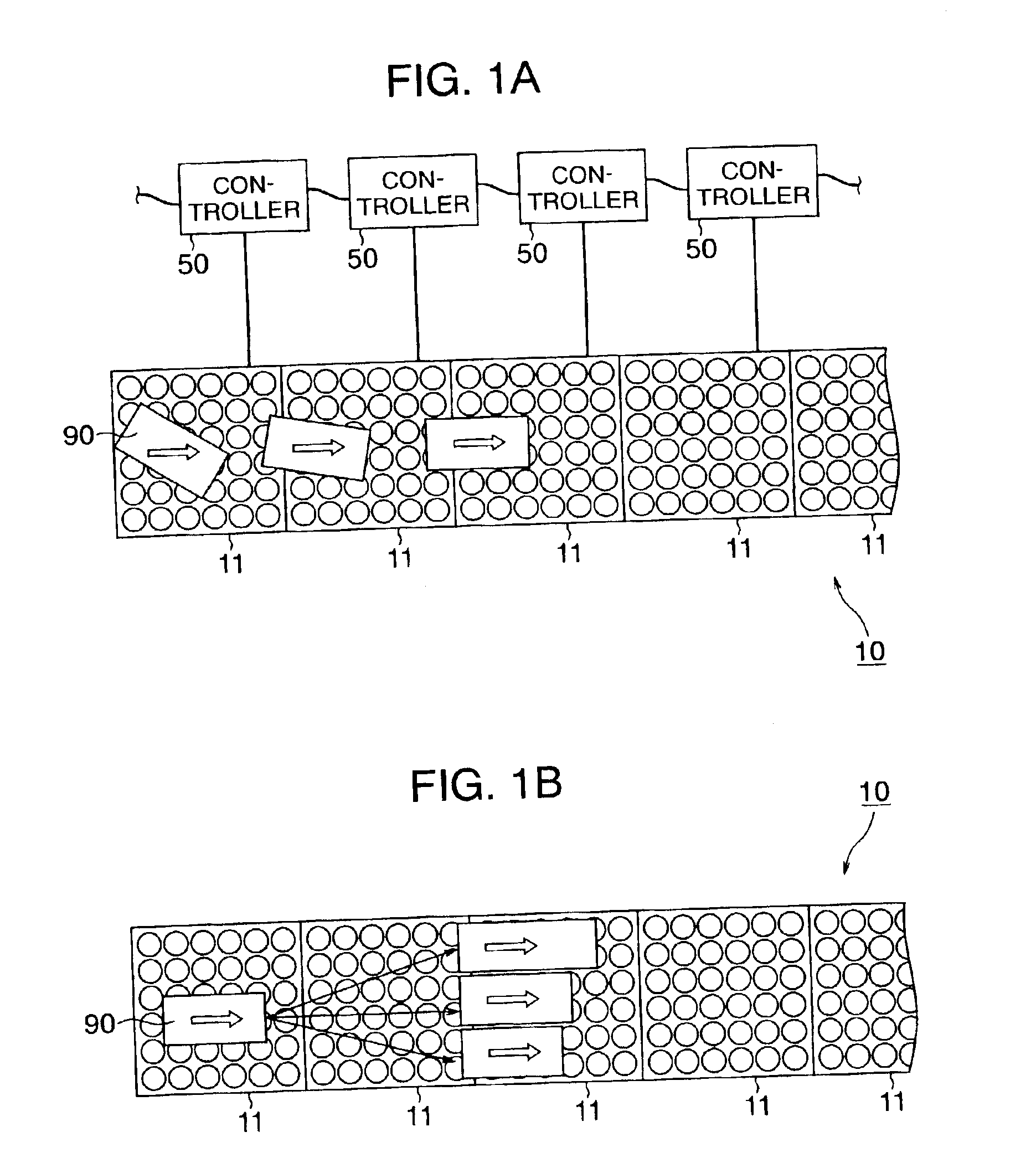
[0067]As shown in FIG. 1A (which is a plan view), a conveying system 10, embodying the present invention, comprises a plurality of conveying modules (“conveying apparatus” of the present invention) 11 arranged in a continuous manner, and can convey an article 90, placed on an upper surface, in a sliding manner. First, the structure of each conveying module 11 is described.

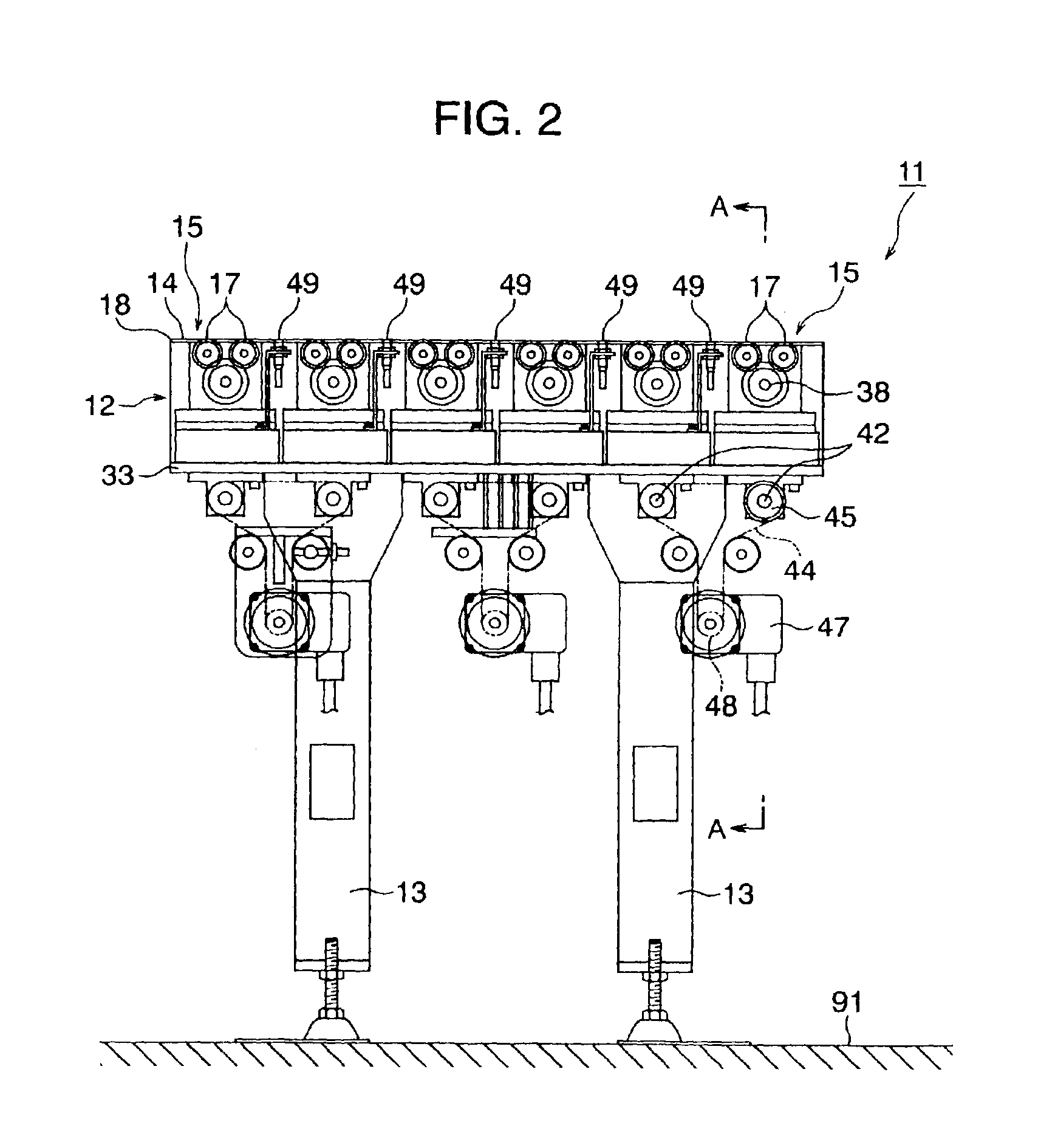
[0068]As shown in FIG. 2, the conveying module 11 includes a table-like fixed base 12. The fixed base 12 includes an upper wall 18 and a lower wall 33 vertically opposed to each other. A plurality of legs 13 extend downwardly from the lower wall 33, and these legs 13 are fixed, for example, to a floor 91 of a warehouse or the like. As shown in FIG. 3, the upper wall 18 has a generally plate-like form of a square shape, and 36 round holes 19 are formed through this upper wall 18, and are arranged in 6 columns and 6 row...

Example

[Second Embodiment]

[0103]This embodiment is shown in FIGS. 17 to 21. Only those portions of this embodiment different in construction from the first embodiment will be described below, and those portions identical in construction to the first embodiment will be designated by identical reference numerals, respectively, and repeated description thereof will be omitted.

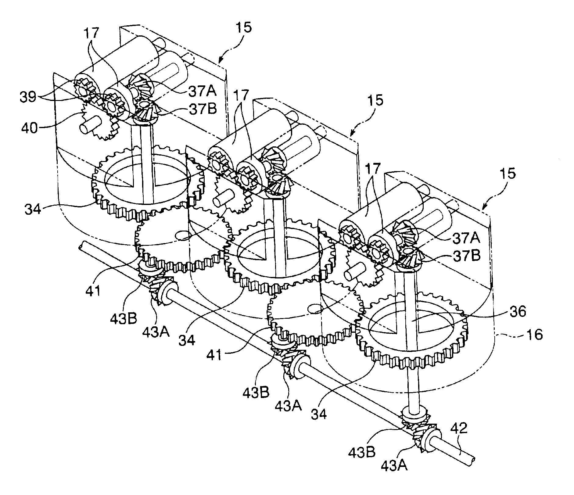
[0104]As shown in FIG. 17, a lower wall 33′ of a fixed base 12, provided at a conveying module 11′ (“conveying apparatus” of the present invention), is in the form of a flat plate, and has a plurality of idle gear-mounting holes 33F provided around each mounting hole 33A in which a feed portion 15′ is mounted. An upper surface of the lower wall 33′ and inner surfaces of the mounting holes 33A are covered with a sliding metal 32M. For example, the idle gear-mounting hole 33F is disposed between any two mounting holes 33A and 33A adjacent to each other in a lengthwise direction, and also the idle gear-mounting hole 33F is ...


PUM


Abstract

There are disclosed a conveying apparatus and a conveying system in which a force is efficiently transmitted to an article so as to smoothly convey the article in an arbitrary direction. In each of feed portions 15 provided at a conveying apparatus 10, 11 of the invention, a twist gear 34 is mounted on a twist base 16, and is disposed below feed rollers 17, and therefore the degree of freedom of the configurations of the twist gear 34 and feed rollers 17 are higher as compared with a conventional construction in which a feed roller is provided within a twist gear. Therefore, a compact design of the twist gear 34 can be achieved, and also the feed portions 15 and 15 can be disposed closer to each other as compared with the conventional construction. And besides, a large-size design of the feed rollers 17 can be achieved, so that an area of contact of the feed rollers 17 with the article can be increased. As a result, the force can be efficiently transmitted to the article 90 from each of feed portions so as to smoothly convey the article in an arbitrary direction.

Description

BACKGROUND OF THE INVENTION[0001]1. Field of the Invention[0002]This invention relates to a conveying apparatus and a conveying system in which a plurality of feed portions are arranged two-dimensionally in a distributed manner over a conveying surface, and the feed portions sequentially feed an article so as to move the same to a predetermined position on the conveying surface.[0003]2. Related Art[0004]FIG. 22 shows a feed portion 1 provided in a conventional conveying apparatus of the type described. In this feed portion 1, a rotation shaft 3 is provided within a twist gear 2 rotatable about a vertical axis, and a feed roller 4 and an output bevel gear 5 are fixedly mounted on the rotation shaft 3. An input bevel gear 6 in mesh with a lower side of the output bevel gear 5 is driven by a servomotor so as to rotate the feed roller 4, while a spur gear 7 in mesh with the outer periphery of the twist gear 2 is driven by a servomotor so as to rotate the twist gear 2 (see Patent literat...

Claims


Application Information

Patent Timeline
IPC IPC(8): B65G13/10B65G47/244B65G13/00B65G1/04B65G47/24B65G13/04B65G29/00B65G47/22B65G47/68
CPCB65G1/0478B65G13/10B65G2203/042B65G37/02B65G2207/34
Inventor KANAMORI, HIROSHIYAGUCHI, SHOJIKOMAZAWA, YUICHI
Owner ASAHI SEIKI INDUSTRIES
Why Eureka
Try Eureka