Digital observation system

Active Publication Date: 2007-12-25
STAR
View PDF12 Cites 3 Cited by
  • Summary
  • Abstract
  • Description
  • Claims
  • Application Information

AI Technical Summary

Benefits of technology

[0006]The present invention achieves technical advantages as a digital observation system and method for processing and transmitting video data between a video camera (or video cameras) and a base unit via, for example, a communication protocol that is compliant with Ethernet physical drivers for transmitting and receiving data at around 100 Mbs. With such a digital observation system, video is captured at a sensor in the video camera, digitally processed and transmitted, thus overcoming the aforementioned limitations and allowing unique features to be added. Images and other data may be transmitted efficiently (in their native format), with reduced overhead (header information can be minimized), and in a non-compressed format (since transmission occurs at or below 100 Mbs).
[0007]In one embodiment, a digital observation system comprises a digital camera and a base unit. The digital camera includes a charge coupled device (CCD) image sensor memory, a CCD image sensor, a correlated double sampling (CDS) circuit, and a physica

Problems solved by technology

This type of conventional system has several limitations including noisy video, low interlaced resolution, slow f

Method used


Image

  • Digital observation system
  • Digital observation system
  • Digital observation system

Examples


Example

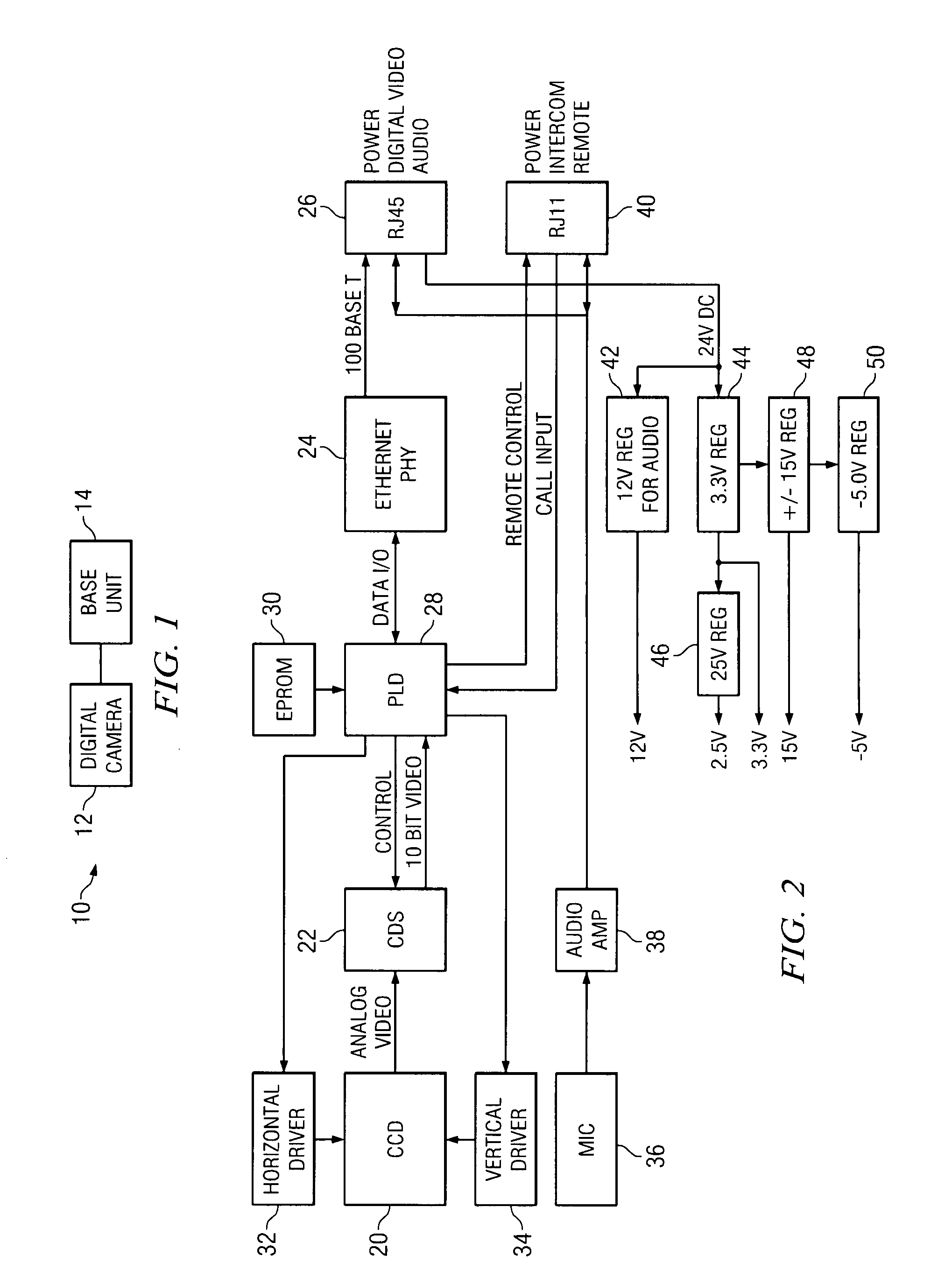
[0015]Referring now to FIG. 1, a digital observation system 10 of the present invention is presented. The system 10 includes at least one digital camera 12 coupled to at least one base unit 14 via, for example, an Ethernet connection.

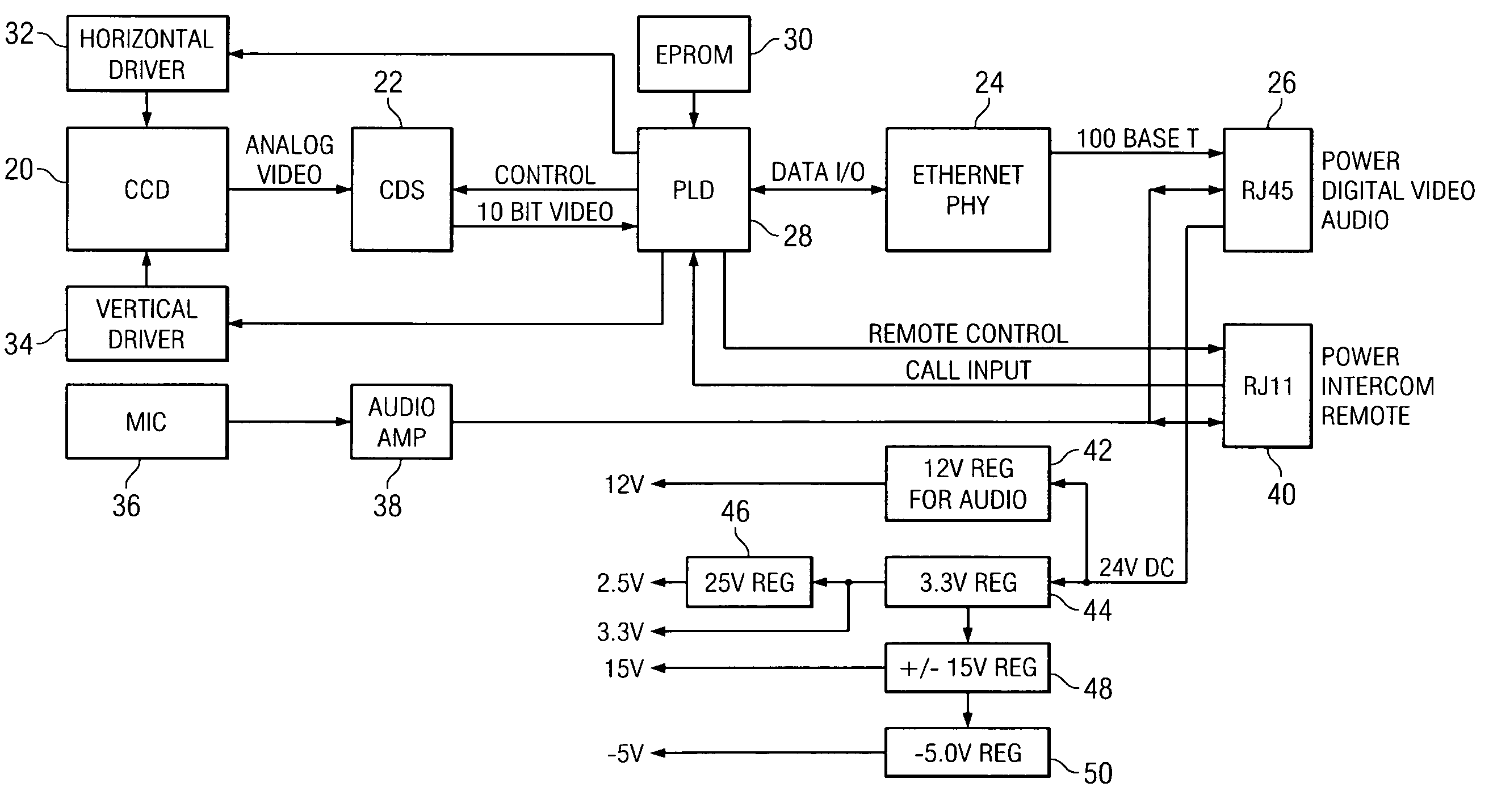
[0016]Referring now to FIG. 2, the digital camera 12 is presented. The digital camera 12 includes a charge coupled device (CCD) image sensor 20 which includes a CCD memory (not shown), a correlated double sampling (CDS) circuit 22, and a physical interface 24. Although the image sensor preferably used by the present invention is a CCD image sensor, a complementary metal oxide semiconductor (CMOS) image sensor may also be used. The CCD image sensor is a collection of tiny light-sensitive diodes, called photosites, which convert photons (light) into electrons (electrical charge). Each photosite is sensitive to light, wherein the brighter the light that hits a single photosite, the greater the electrical charge that will accumulate at that site. The value ...


PUM


Abstract

A digital observation system and method for processing and transmitting video data between a video camera, or video cameras, and a base unit. The video data is transmitted, for example, by a communication protocol that is compliant with Ethernet physical drivers for transmitting and receiving data at around 100 Mbps. Video is captured at a sensor in the video camera, digitally processed and transmitted, thus overcoming limitations associated with analog processing and allowing unique features to be added. Images and other data may be transmitted efficiently in their native format, with reduced overhead, and in a non-compressed format due to the data transmission rate at or below 100 Mbps.

Description

RELATED APPLICATIONS[0001]The present invention is related to patent application Ser. No 10 / 202,968 titled DIGITAL TRANSMISSION SYSTEM, to patent application Ser. No. 10 / 202,668 titled DIGITAL CAMERA SYNCHRONIZATION, and to patent application Ser. No. 10 / 202,257 titled UNIVERSAL SERIAL BUS DISPLAY UNIT. These applications are commonly assigned, commonly filed, and are incorporated by reference herein.[0002]1. FIELD OF THE INVENTION[0003]The present invention relates to observation systems and, more particularly, to a digital observation system comprising a digital camera and a base unit.[0004]2. BACKGROUND OF THE INVENTION[0005]A conventional observation system is based on standard analog cameras attached, via a specialized cable, to a Cathode Ray Tube monitor for display. All video processing is performed in the analog domain. This type of conventional system has several limitations including noisy video, low interlaced resolution, slow frame rate or image roll during switching, li...

Claims


Application Information

Patent Timeline
IPC IPC(8): H04N5/225H04N7/18
CPCH04N7/183
Inventor COOPER, ALAN NEALFRITZ, CHRISTOPHER MICHAELEXNER, JAMES WALTER
Owner STAR
Why Eureka
Try Eureka