Image capture system and method using a common imaging array

a technology of image capture system and imaging array, which is applied in the direction of exposure control, printers, camera focusing arrangement, etc., can solve the problems of color aliasing of bayer cfa, resolution and sensitivity problems, poor reliability and repeatability

Inactive Publication Date: 2005-05-10
SYMBOL TECH LLC
View PDF5 Cites 104 Cited by
  • Summary
  • Abstract
  • Description
  • Claims
  • Application Information

AI Technical Summary

Benefits of technology

[0021]To prevent light captured by one of the lenses from reaching that part of the common array reserved for use for light captured by the other of the lenses, a light baffle is used in an interior of a support in which the array is contained. The baffle may be coated with a light-absorbent coating.

Problems solved by technology

Although generally satisfactory for its intended purpose, the Bayer CFA has color aliasing, resolution and sensitivity problems due in part to the fact that the cells for the different colors are at different locations.
However, all of these designs require moving parts which are complex to assemble, and often exhibit poor reliability and repeatability.

Method used


Image

  • Image capture system and method using a common imaging array
  • Image capture system and method using a common imaging array
  • Image capture system and method using a common imaging array

Examples


Embodiment Construction

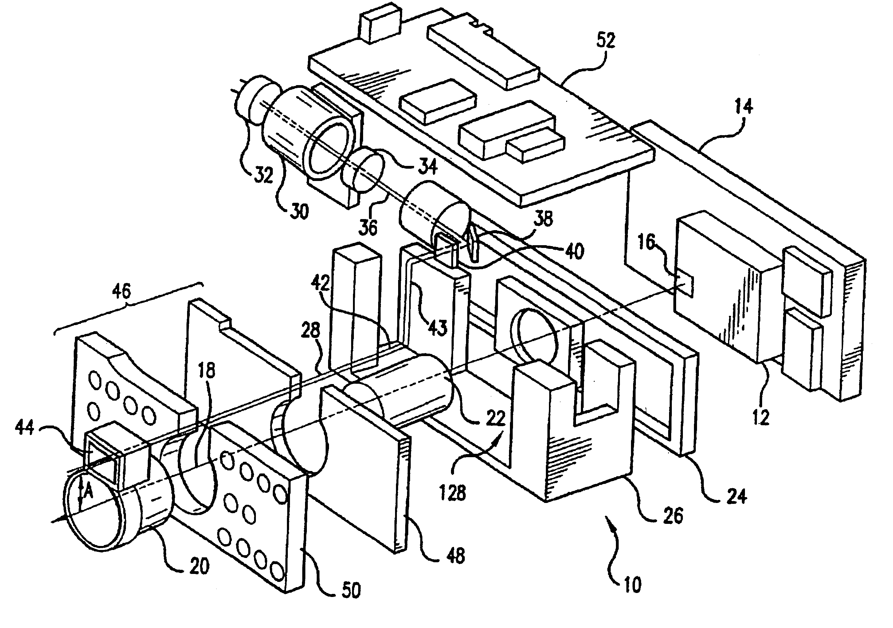
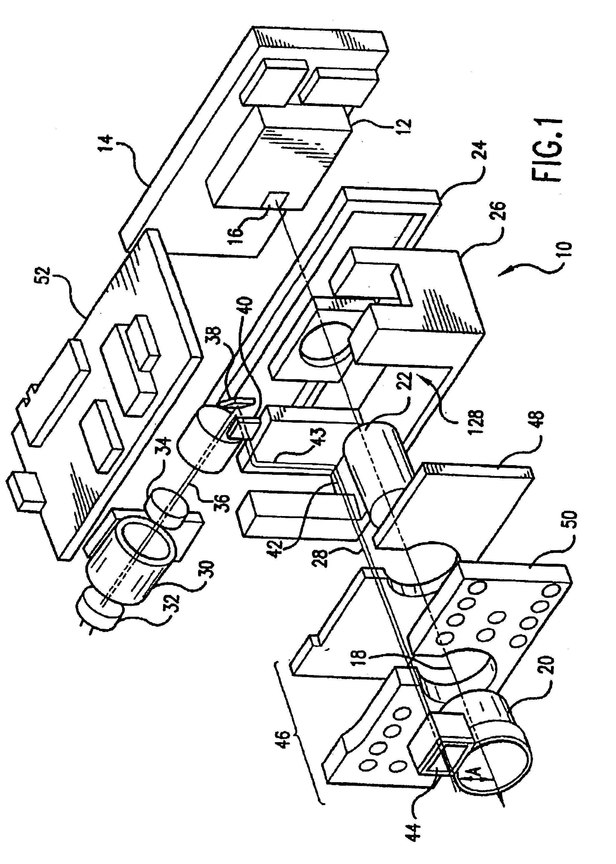
[0034]Referring now to the drawings, FIG. 1 illustrates an imaging engine 10 of a preferred embodiment of the present invention. The figure is an exploded view illustrating certain optical paths and subsystems of the imaging engine. As shown, the imaging engine includes various circuit boards, optical elements and chassis elements. A packaged image sensor array 12 is located on an image sensor board 14. The image sensor board 14 may also contain image acquisition circuitry associated with the image sensor array 12. In a preferred embodiment, the imaging array 12 has a window 16 through which an incident image is received. The array converts the incident light into electrical signals which are processed as described below. A suitable array is disclosed in U.S. Pat. No. 5,965,875, the contents of which are incorporated herein by reference thereto. Other suitable arrays are CCD and CMOS arrays.

[0035]A line 18 indicates the principal optical axis of the image sensor array 12 of the imag...


PUM


Abstract

An image of a target in a far-field range of working distances relative to an image capture system is focused at a first group of sensors in a common, two-dimensional, array of sensors, and an image of an optical code in a near-field range of working distances relative to the system is focused at a second group of sensors in the array. The same array is shared in a portable apparatus capable of capturing target images and optical code images without moving any optical components.

Description

CROSS REFERENCE TO RELATED APPLICATION[0001]This application claims the priority of U.S. Provisional Patent Application Ser. No. 60 / 365,853, filed Mar. 20, 2002.BACKGROUND OF THE INVENTION[0002]1. Field of the Invention[0003]The present invention generally relates to image capture systems and methods and, more particularly, to capturing a full color or monochrome image of a target and / or capturing a monochrome image of an optical code symbol to be read using a common imaging array, and especially by using an imaging array of pixel sensors each operative for measuring each of three primary colors of incident light at the same location of a respective pixel sensor.[0004]2. Description of the Related Art[0005]Optical codes are patterns made up of image areas having different light-reflective or light-emissive properties, which are typically assembled in accordance with a priori rules. The term “barcode” is sometimes used to describe certain kinds of optical codes. The optical propertie...

Claims


Application Information

Patent Timeline
Patent Type & Authority Patents(United States)
IPC IPC(8): G06K7/10
CPCG06K7/10722G06K7/1092G06K7/10851G06K7/10811
Inventor BIANCULLI, THOMAS D.PATEL, MEHUL M.
Owner SYMBOL TECH LLC
Why Eureka
Try Eureka