Leveling shoe

a leveling shoe and leveling technology, applied in the field of leveling shoes, can solve the problems of uneven load distribution of the adjusting wedge, additional moment loading and stress, affecting the stability of the leveling shoe, etc., and achieve the effect of improving stability and simple and cheap manufacturing

Inactive Publication Date: 2005-05-10
NIVELL
View PDF17 Cites 21 Cited by
  • Summary
  • Abstract
  • Description
  • Claims
  • Application Information

AI Technical Summary

Benefits of technology

[0007]This invention is based on the problem of creating a levelling shoe which is simple and cheap to manufacture and displays improved stability.
[0009]Because the adjusting wedge device, in addition to the adjusting wedge, displays a further counterwedge, where both wedges can be moved reciprocally towards or away from each other such that due to the fact that in every position their supporting surfaces for the supporting plate are arranged symmetrically to a plane perpendicular to the base surface, in which plane the axis of the connecting bolt also runs, the enormous, unilaterally-acting forces, as occur in the case of the levelling shoe according to CH-PS 652 186, are eliminated and the load is evenly distributed over both wedges. The screw spindle provided with two threaded parts displaying the same thread pitch, but opposing direction of pitch, arranged perpendicular to the plane of symmetry of the wedges and parallel to the base surface no longer requires an expensive axial bearing, as was previously necessary, since the axial forces transferred onto the two thread parts counteract each other and thus cancel each other out. Although, in place of one adjusting wedge, two wedges are used, the levelling shoe is simpler and cheaper to manufacture than ordinary levelling shoes.
[0010]In an especially advantageous fashion, the screw spindle engages with one threaded part in the adjusting wedge and with the other threaded part in a plate arranged on the other side of the adjusting wedge from the counterwedge. The plate is permanently attached to the counterwedge. This attachment is made advantageously via two connecting bolts projecting through the adjusting wedge each surrounded by a spacer sleeve guided so as to slide into the adjusting wedge, which connecting bolts are arranged parallel to the base surface and also serve as guide elements for the wedge. Advantageously the two connecting screws are arranged on both sides and at the same distance from a plane perpendicular to the base surface in which the screw spindle axis runs. As the result of this, a centering sleeve screwed with the base plate can be placed centrally between the two connecting bolts, on which the supporting plate is vertically guided, and which is provided to accept the connecting bolt connecting the object with the base plate. The central arrangement of both the centering sleeve and also the screw spindle considerably increases the stability of the levelling shoe, especially where heavy loads or changing loads are involved. Advantageously both wedges, in the position corresponding to the maximum height adjustment of the supporting plate, come to rest on reciprocal stop faces, so that this end position is clearly defined.

Problems solved by technology

When this occurs, especially when raising large loads, enormous lateral forces are exerted on the stop element, which can even cause breakage of the latter.
Both the screw spindle and the connecting bolt, however, are located at a distance from a central plane perpendicular to the base surface (i.e. a gravitational plane), which results in an uneven load distribution on the adjusting wedge and an additional moment loading and stress on the screw spindle and / or the bearing, and additionally affects the stability of the levelling shoe.
A further disadvantage lies in the fact that the adjusting wedge displays a relatively complicated form (U-shape, precise seat surfaces and guidance surfaces, etc.).
Especially when the levelling shoe is used for large heavy loads, for example, machine tools, which are also exposed to powerful changing loads, so that it is vital for the adjusting wedge to be extremely rigid, and the adjusting wedge must be manufactured precisely from steel, and thus the levelling shoe is expensive to produce.

Method used


Image

  • Leveling shoe
  • Leveling shoe

Examples


Embodiment Construction

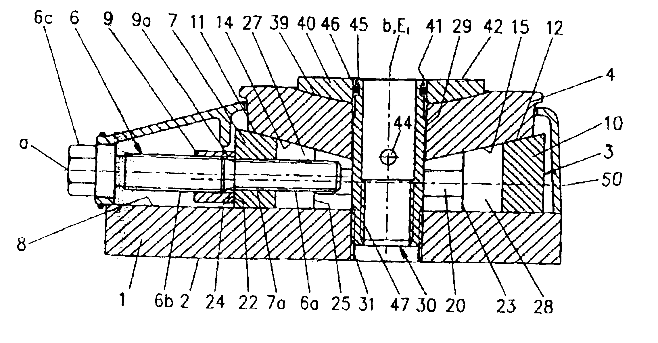
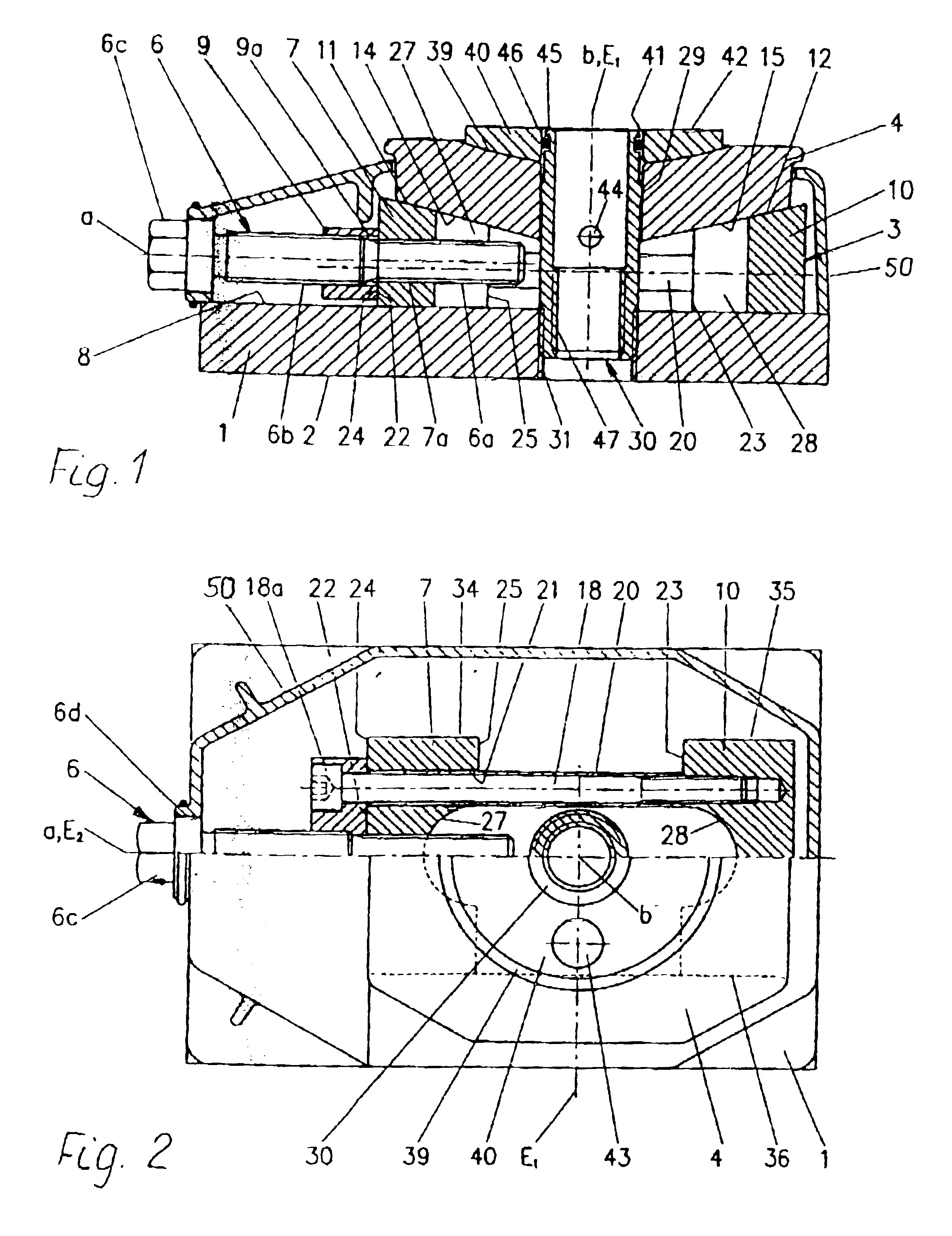
[0014]According to FIG. 1, a levelling shoe displays a base plate 1 with a base surface 2 resting on the floor and also a supporting plate 4 for an object, not shown, for example a machine or a device. The supporting plate 4 is adjustable in height perpendicular to the base surface 2 by means of an adjusting wedge device 3. The adjusting wedge device 3 comprises a screw spindle 6, the axis (a) of which is arranged parallel to the base surface 2 and which displays a first threaded part 6a which engages in a thread bore hole 7a of an adjusting wedge 7 arranged moveably on an upper surface 8 of the base plate 1. The screw spindle 6 is further provided with a second threaded part 6b, which displays the same thread pitch, but an opposing direction of the threads with respect to the first threaded part (left / right thread). The second threaded part 6b engages in a thread bore hole 9a of a plate 9, which—as described below in more detail—is also permanently attached to a counterwedge 10 whi...


PUM


Abstract

A leveling shoe with a base plate (1) that has a base surface (2) and with a support plate (4) for an object that can be adjusted by means of an adjusting wedge device (3) in rectangular height direction relative to the base surface (2). The leveling shoe has an improved stability and is yet simple and inexpensive in its production. The adjusting wedge device (3) includes two wedges (7,10) that can be moved towards or away from each other by actuating a screw spindle (6). The wedges are provided with support surfaces (11,12) for the support of the plate (4). The support surfaces (11,12), in every position of the wedges (7,10), are disposed symmetrically with respect to a first plane (E1) that is perpendicular to the base surface. The screw spindle axis (6) is provided with two screw parts (6a, 6b) that have identical thread pitches but opposite thread directions.

Description

BACKGROUND OF THE INVENTION[0001]1. Field of the Invention[0002]The invention concerns a levelling shoe.[0003]2. Description of Related Art[0004]A levelling shoe of this type is prior art from, for example, CH-PS 652 186. This levelling shoe also displays a base plate and a supporting plate for an object, for example a machine or a device. The supporting plate can be displaced in a perpendicular direction relative to a base surface of the base plate by means of an adjusting wedge device. The adjusting wedge device comprises an adjusting wedge which in top view is essentially U-shaped, displaying a middle section and two wings which can be displaced by means of a screw spindle transversely to the vertical direction and is at the same time guided with a pair of lower supporting surfaces inclined towards each other on corresponding surfaces of the base plate. The direction of displacement of the adjusting wedge is inclined with respect to the base surface. Both the middle section and t...

Claims


Application Information

Patent Timeline
Patent Type & Authority Patents(United States)
IPC IPC(8): F16M7/00
CPCF16M7/00
Inventor BIZAJ, ROGER
Owner NIVELL
Why Eureka
Try Eureka