

Static field controlling method and MRI apparatus
a static field and control method technology, applied in the field of static field control and magnetic resonance imaging, can solve the problems of adjustable range or the trade-off of the uniformity of the static field, and achieve the effect of preventing the disturbance of the static field
- Summary
- Abstract
- Description
- Claims
- Application Information
AI Technical Summary
Benefits of technology
Problems solved by technology
Method used
Image


Examples
first embodiment
[First Embodiment]
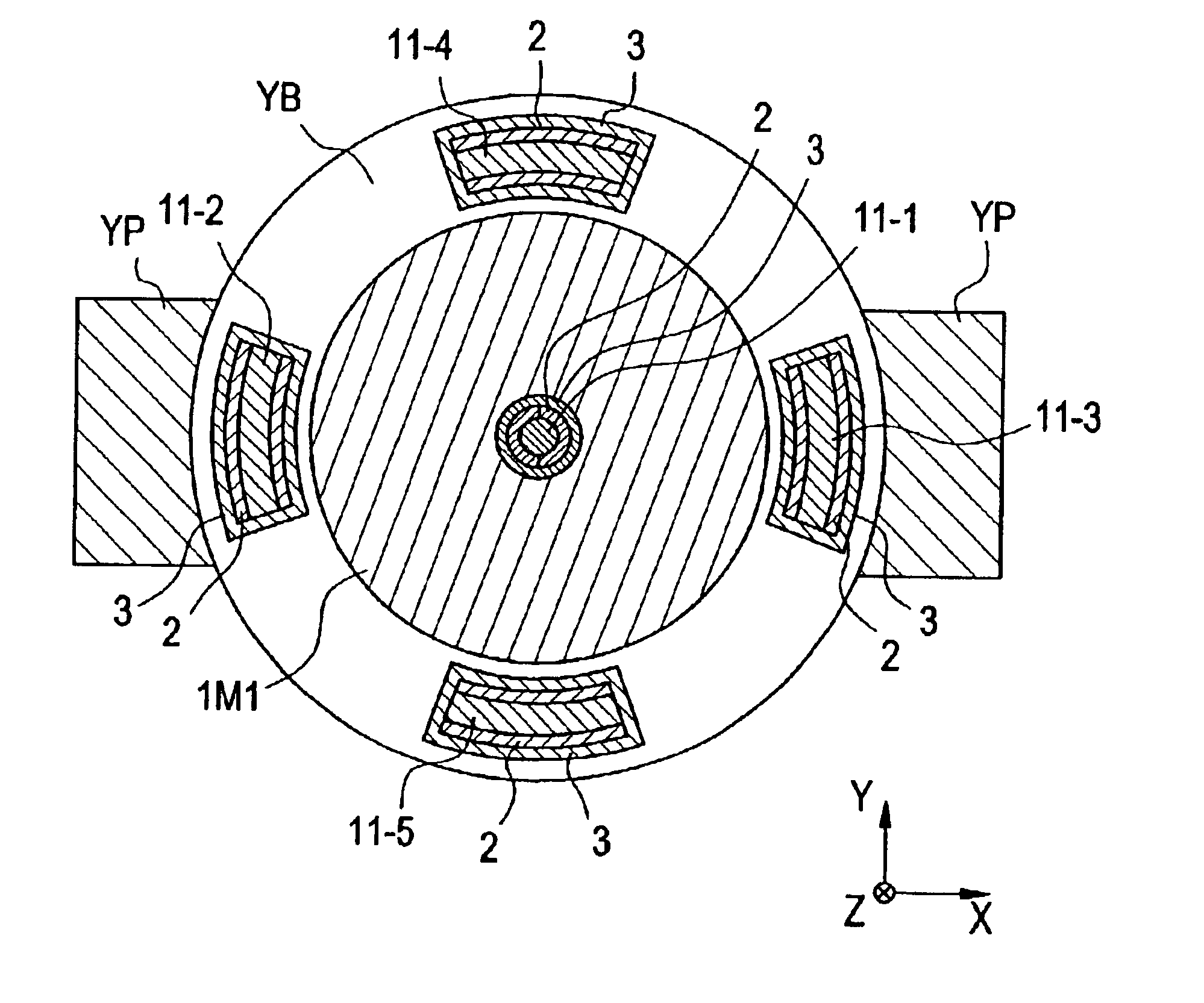
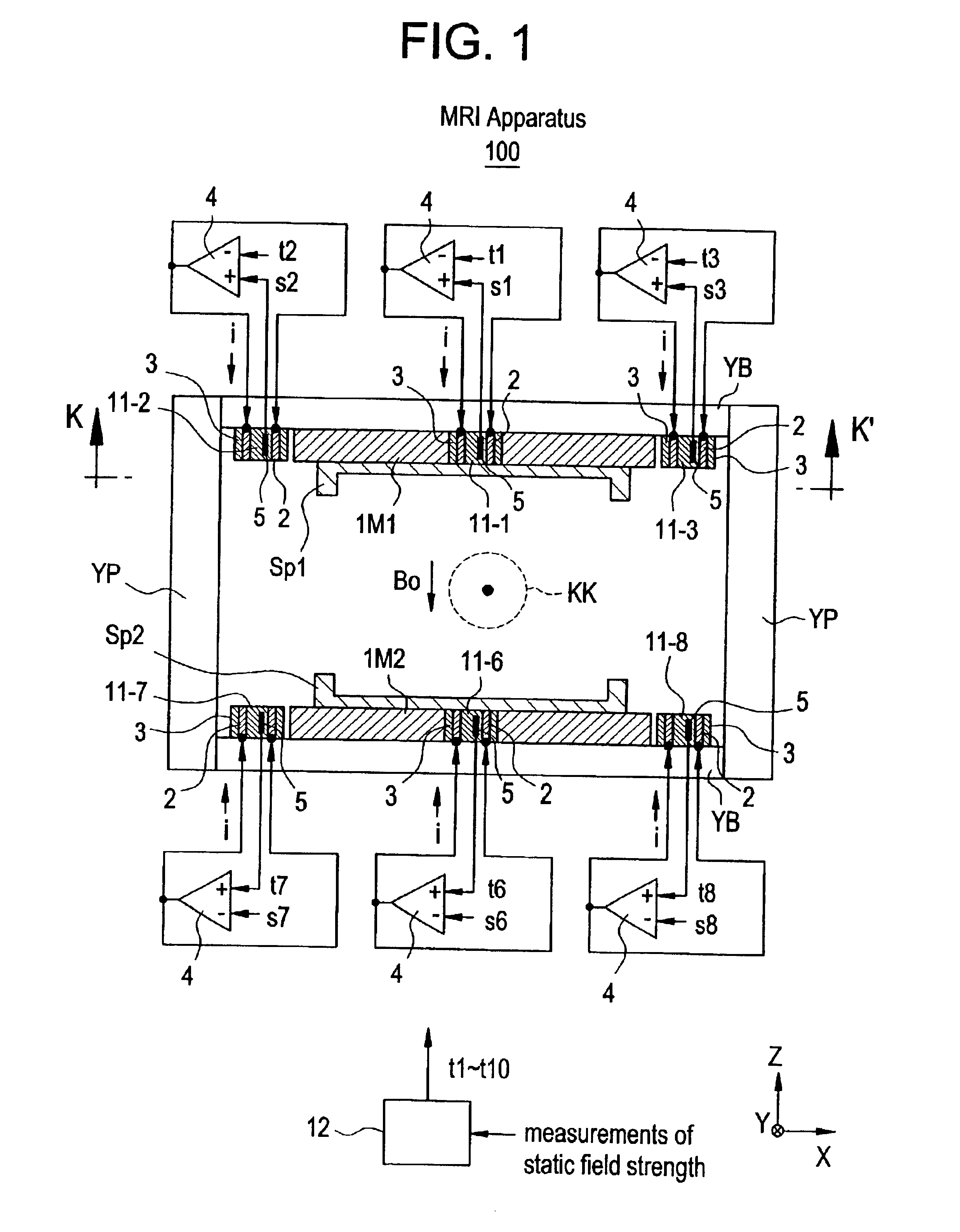
[0061]Now referring to FIG. 1, which shows a partial cross-sectional view of an MRI apparatus in accordance with first preferred embodiment of the present invention. Also referring to FIG. 2, which shows a cross-sectional view taken along with the line K-K′ of FIG. 1.
[0062]The MRI apparatus 100 is an open-type MRI apparatus, which generates static field Bo in the vertical direction from the permanent magnets, namely the permanent magnets 1M1 and 1M2 mounted on top and bottom at opposite locations.
[0063]On the surface of the respective permanent magnets 1M1 and 1M2 deflector Sp1 and Sp2 are mounted which may improve the uniformity of the static field Bo in the imaging area KK.
[0064]A magnetic circuitry may be formed by the permanent magnets 1M1 and 1M2, the deflector Sp1 and Sp2, base yokes YB, and columnar yokes Yp. The material used for the permanent magnets 1M1 and 1M2 may include, for example Neodymium magnetic materials (Nd—Fe—B), Samarium-Cobalt magnetic mater...
second embodiment
[Second Embodiment]
[0085]Now referring to FIG. 6, there is shown a partially cross-sectional view of an MRI apparatus in accordance with second preferred embodiment of the present invention. Also referring to FIG. 7, which shows a cross-section taken along with the line K-K′ of FIG. 6.
[0086]In this MRI apparatus 200, the permanent magnet 1M1 and base yoke YB may have at many positions a screw hole opened, namely static field regulation unit mounting means 20-1 to 20-10, which optionally attach and detach a static field regulation unit 21-1 to 21-10 selected from a group constituted of a plurality of types of units (21α, 21β, 21γ shown in FIG. 8).
[0087]As shown in FIG. 8(a), the static field regulation unit 21α may be formed from a nonmagnetic socket 210α as a hollow cylinder element and in the outer shape of a threaded screw, and a magnetic core 211α extending through the center of the socket and in the form of solid cylinder of diameter r1.
[0088]As shown in FIG. 8(b), static field ...
third embodiment
[Third Embodiment]
[0096]An MRI apparatus in accordance with the third preferred embodiment of the present invention uses a static field regulation unit 31 as shown in FIG. 9, instead of the static field regulation unit 21 (see FIG. 8) used in the above second preferred embodiment. More specifically, a static field regulation unit 31 assembly will be used, which is assembled by a last stage ring 310 in the form of hollow cylinder having threaded into the center bore a first stage ring 311 in the form of hollow cylinder having threaded into the center bore a core 312 in the form of solid cylinder.
[0097]As shown in FIG. 10(a1) and (b1), either one of last stage ring 310A of magnetic material or last stage ring 310B of nonmagnetic material will be selected for the last stage ring 310.
[0098]As shown in FIG. 10(a2) and (b2), either one of first stage ring 311A of magnetic material or first stage ring 311B of nonmagnetic material will be selected for the first stage ring 311.
[0099]As shown...
PUM
 Abstract
Description
Claims
Application Information