Highly sensitive cross axis accelerometer

a cross-axis accelerometer, high-sensitivity technology, applied in the direction of acceleration measurement using interia force, speed/acceleration/shock measurement, instruments, etc., can solve the problems of limited electronic sensors presently used, oil well monitoring presents certain challenges for conventional sensors, and the on-board electronics of such sensors must operate in a hostile environmen

Inactive Publication Date: 2005-05-10
OPTOPLAN
View PDF28 Cites 69 Cited by
  • Summary
  • Abstract
  • Description
  • Claims
  • Application Information

AI Technical Summary

Benefits of technology

[0010]The present invention is generally directed to a fiber optic accelerometer that may be used within a harsh environment (i.e., high temperature, pressure, shock and / or vibration) such as oil and / or gas wells, engines, combustion chambers, etc.

Problems solved by technology

The monitoring of oil wells presents certain challenges for conventional sensors because of the harsh environment in terms of high pressures and temperatures.
The presently used electronic sensors are limited for several reasons.
First, the on-board electronics of such sensors must operate in a very hostile environment, which includes high temperature, high vibration and high external hydrostatic pressure.
Second, electronics' inherent complexity renders them prone to many different modes of failure.
Because early failure of the sensors results in time-consuming and expensive well intervention, such failures have traditionally caused a less than acceptable level of reliability when electronic sensors are used to monitor oil wells.
There are numerous other problems associated with the transmission of electrical signals within well bores.
It is extremely difficult to seal the required insulated cables against exposure to well bore fluids, which are at high temperatures, high pressures, and are very corrosive.
Electrical conductors damaged by the fluids that penetrate the insulating materials around the electrical conductors will typically short-circuit the electrical signals.
Additionally, electrical transmissions are subject to electromagnetic interference in many production operations.
Piezoelectric accelerometers typically suffer from the above-identified problems common to electronic sensors.
Additionally, most high performance piezoelectric accelerometers require power at the sensor head.
Also, multiplexing of a large number of sensors is cumbersome and tends to incur significant increases in weight and volume with a decrease in reliability.
Some of these fiber optic accelerometers have displayed very high acceleration sensitivity (up to 104 radians / g), but tend to utilize a sensor design that is impractical for many applications.
For example, sensors with a very high sensitivity typically have a seismic mass greater than 500 grams, which seriously limits the frequency range in which the device may be operated.
Additionally, these devices are so bulky that their weight and size renders them useless in many applications.
Other fiber optic accelerometers suffer from high cross-axis sensitivity, low resonant frequency.
Many fiber optic accelerometers require an ac dither signal or tend to be bulky (>10 kg), expensive and require extensive wiring and electronics.
Even optical interferometers designed of special material or construction are subject to inaccuracies because of the harsh borehole environment and because of the very tight tolerances in such precision equipment.

Method used


Image

  • Highly sensitive cross axis accelerometer
  • Highly sensitive cross axis accelerometer
  • Highly sensitive cross axis accelerometer

Examples


Embodiment Construction

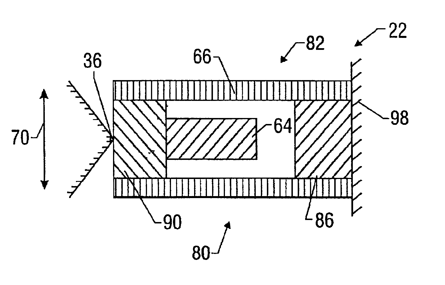
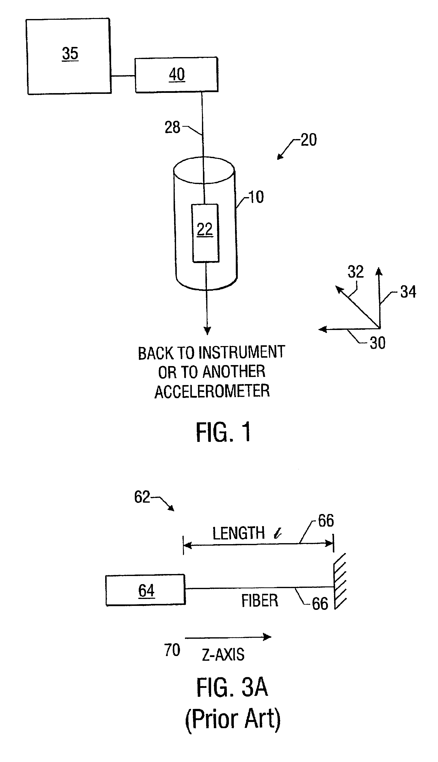
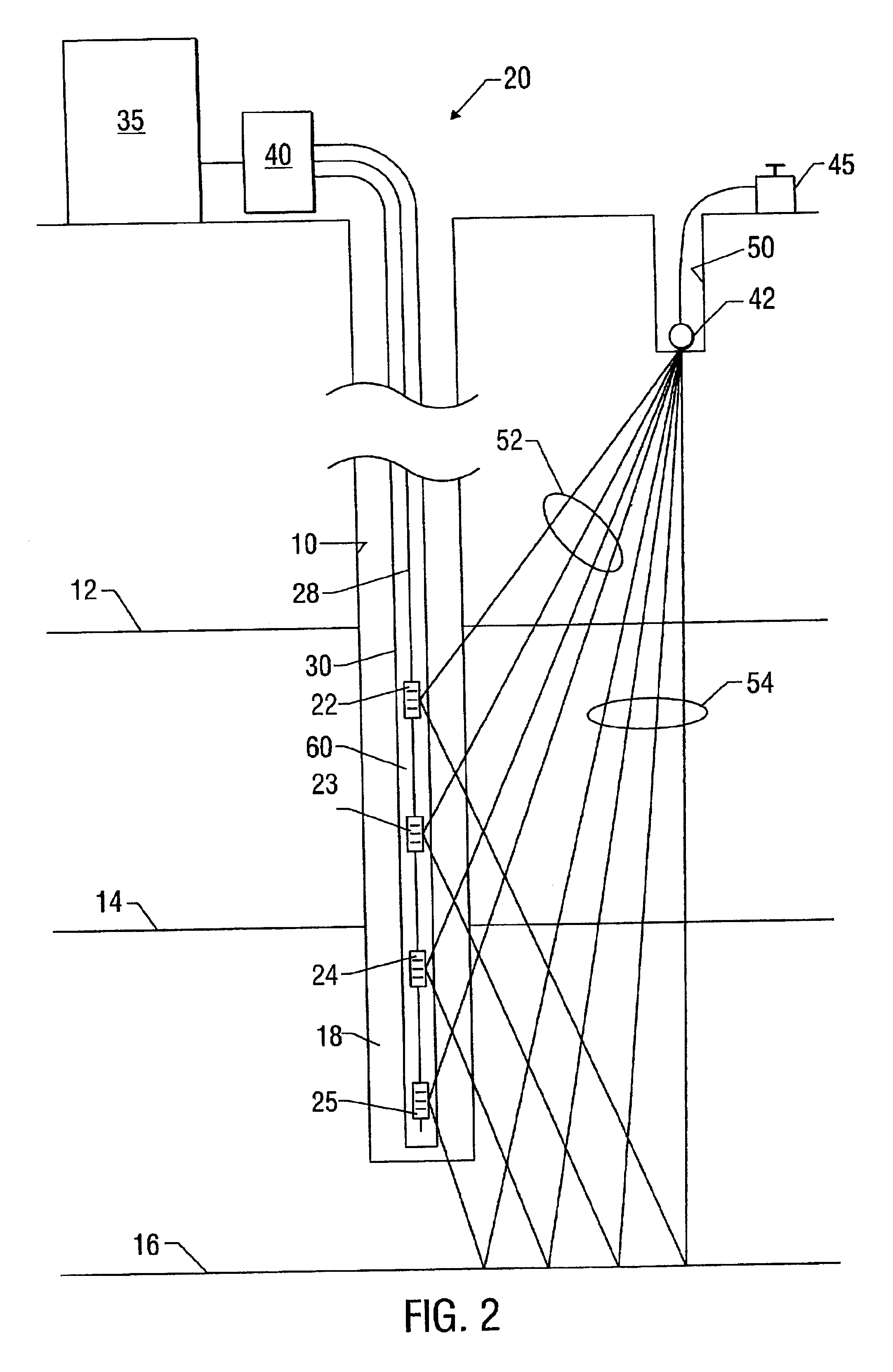
[0038]Referring to FIG. 1, a structure 10 subjected to a hostile environment, such as an oil or gas well borehole, building, bridge, aircraft, pump or other structure or component subjected to acceleration has coupled to it at least one highly sensitive accelerometer 22. Accelerometer 22 is part of transmission cable string 20 connected by transmission cable 28 to a signal converter 40 and signal processing equipment 35. The acceleration of structure 10 in any of the three axes 30, 32, 34 is, depending on the orientation of the accelerometer, detected by accelerometer 22. Signal processing equipment 35 may comprise any known instrumentation for processing the electrical, electro-optical, or optical signal of the various embodiments of the present invention.

[0039]In one embodiment of the present invention, accelerometer 22 is mounted within a hermetically sealed vessel (not shown) and is disposed in a harsh environment. The harsh environment may have a high temperature (up to about 1...


PUM


Abstract

A highly sensitive accelerometer for determining the acceleration of a structure includes a mass within a housing rotationally supported by a hinge and opposing support members. The support members are alternately wound around a fixed mandrel and the mass in a pendulum arrangement. At least a portion of one of the support members comprises a transducer capable measuring the rotation of the mass within the housing. An embodiment of the invention employs optical fiber coils as support members for use in interferometric sensing processes. Arrays of such interferometer based accelerometers maybe multiplexed using WDM or similar methods.

Description

CROSS REFERENCE TO RELATED APPLICATIONS[0001]This application claims the benefit of U.S. Provisional Patent Application Ser. No. 60 / 266,667, filed on Feb. 6, 2001 and having the same title and naming the same inventors as this application, which is hereby incorporated by reference in its entirety.TECHNICAL FIELD[0002]This invention relates to highly sensitive accelerometers, and more particularly to a fiber optic based accelerometer.BACKGROUND ART[0003]It is known to monitor the physical characteristics of structures and bodies using sensors. One such application is the monitoring of oil wells to extract such information as temperature, pressure, fluid flow, seismic and other physical characteristics. The monitoring of oil wells presents certain challenges for conventional sensors because of the harsh environment in terms of high pressures and temperatures. Historically the monitoring of oil wells has been dominated by the use of electronic sensors with optical sensors being used to...

Claims


Application Information

Patent Timeline
Patent Type & Authority Patents(United States)
IPC IPC(8): G01P15/08G01P15/093G01V1/18G01V1/16G01P15/12G01P15/03
CPCG01V1/184G01P15/093
Inventor BERG, ARNEKNUDSEN, SVERRE
Owner OPTOPLAN
Why Eureka
Try Eureka