Magnetic locking device

Active Publication Date: 2005-05-10
QUANTA COMPUTER INC
View PDF5 Cites 44 Cited by
  • Summary
  • Abstract
  • Description
  • Claims
  • Application Information

AI Technical Summary

Benefits of technology

[0018]Hence, the magnetic locking device according to the present invention provides a double side close function and a hiding hook function for electronic appliances. The electronic appliance with the magnetic locking device according to the present inv

Problems solved by technology

Because the display of the notebook/tablet dual-purpose PC possesses the hand writing input function and rotation function, the conventional hoo

Method used


Image

  • Magnetic locking device
  • Magnetic locking device
  • Magnetic locking device

Examples


Example

[0025]The following description is of the best presently contemplated mode of carrying out the present invention. This description is not to be taken in a limiting sense but is made merely for the purpose of describing the general principles of the invention. The scope of the invention should be determined by referencing the appended claims.

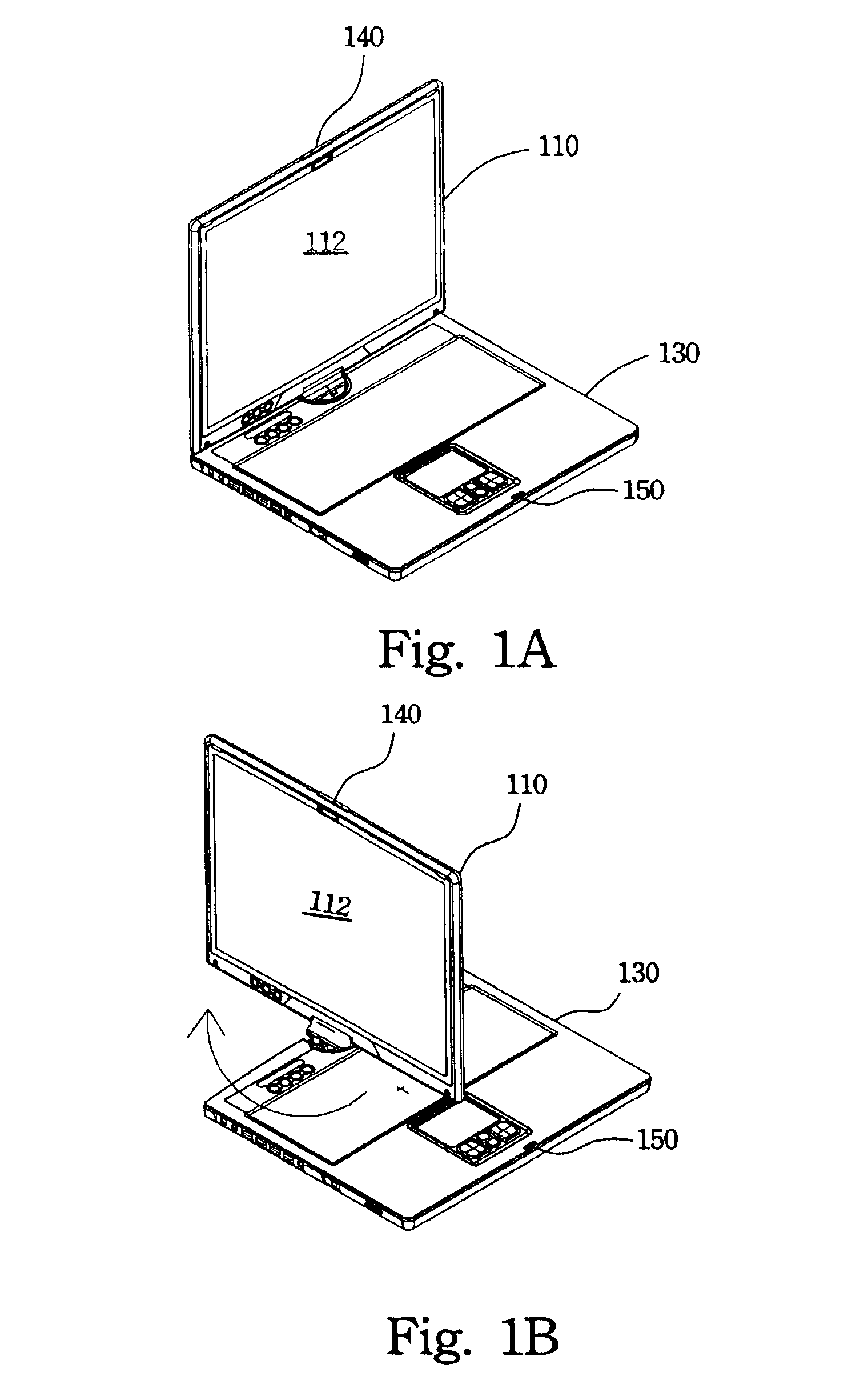
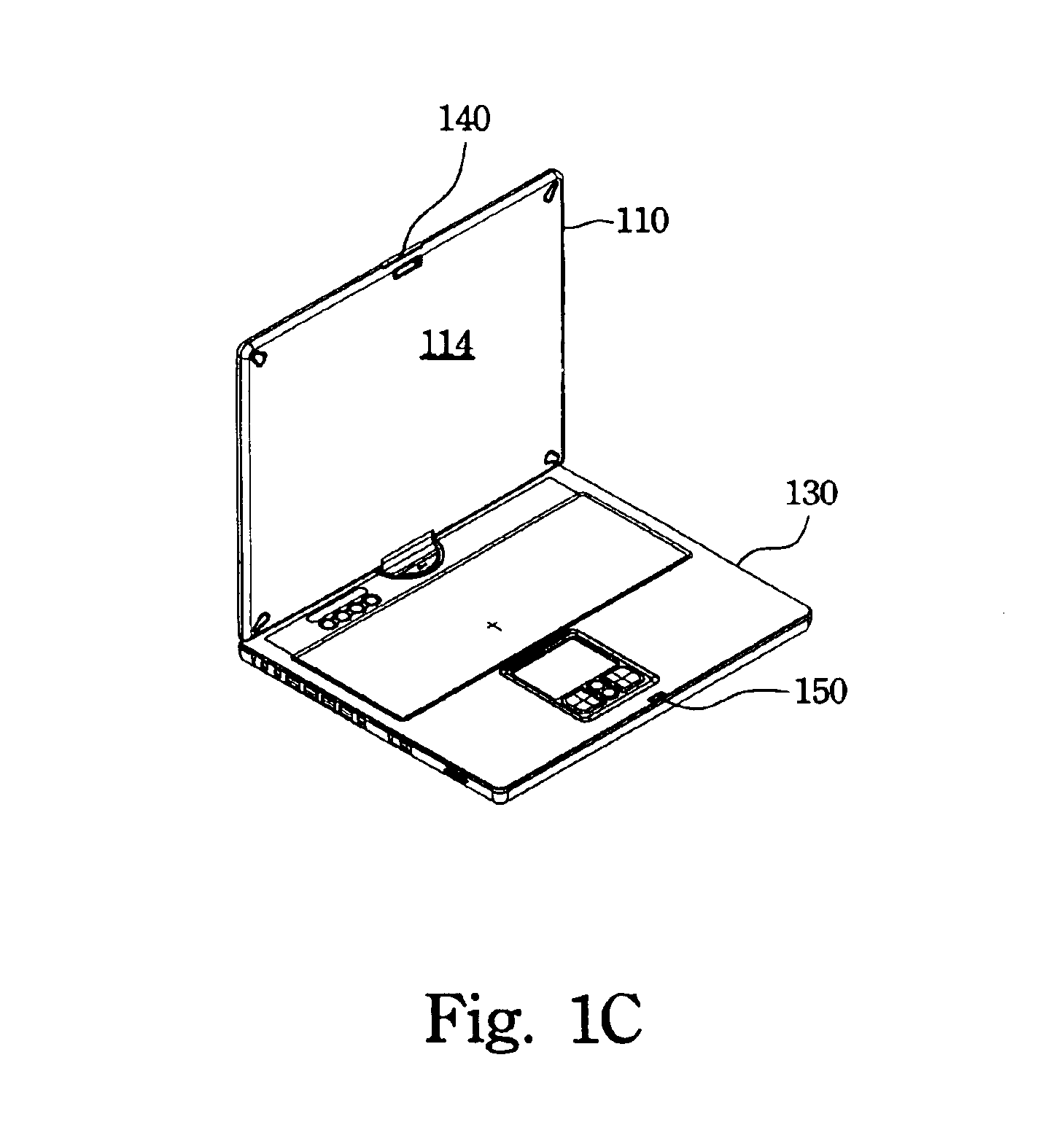
[0026]FIGS. 1A to 1C illustrate a schematic perspective view of a notebook / tablet dual-purpose personal computer having an open display with a magnetic locking device of a preferred embodiment according to the present invention. FIG. 1A illustrates the display as being just opened from a base of a notebook / tablet dual-purpose personal computer. FIG. 1B illustrates the display rotated about 90 degrees from the original position. FIG. 1C illustrates the display rotated about 180 degrees from the original position. Referring to FIGS. 1A to 1C, the notebook / tablet dual-purpose personal computer includes a display 110 and a computer base 130. The disp...


PUM


Abstract

A magnetic locking device is described. The magnetic locking device is utilized for locking an electric device upper cover especially for locking both sides of the display cover of a notebook/tablet dual-purpose personal computer. The magnetic locking device has a lock module and a hook module. The lock module installed in the upper cover has a lock module base, a release button, a magnet, a first bezel and a second bezel. The hook module installed in the electric device base has a hook module base, a spring device, and a hook. The spring device pulls the hook to hide in the electric device base when the hook is not working to improve the electric device appearance and to eliminate interference during operation.

Description

FIELD OF THE INVENTION[0001]The present invention relates to a magnetic locking device and especially to a magnetic locking device for a notebook / tablet dual-purpose personal computer.BACKGROUND OF THE INVENTION[0002]Recently, liquid crystal displays (LCD) have been widely applied in electrical products, due to the rapid progress of optical technology and semiconductor technology. Moreover, with the advantages of high image quality, compact size, light weight, low driving voltage, and low power consumption, LCDs have been introduced into portable computers, personal digital assistants, color televisions, and are gradually replacing the cathode ray tubes (CRT) used in conventional displays. LCDs are becoming the mainstream display apparatus.[0003]A conventional display of a notebook computer is disposed in the upper cover of the notebook computer. The display demonstrates information and images thereon when the upper cover of the notebook computer is opened. The upper cover and a bas...

Claims


Application Information

Patent Timeline
IPC IPC(8): E05B63/24E05B63/00E05C19/00E05C19/16E05C5/00E05B63/04G06F1/16
CPCE05B63/248G06F1/1679E05C19/163G06F1/162E05C5/00E05B63/042Y10T292/11
Inventor CHEN, WEN-HSIANGYANG, KUO-CHANGCHANG, JUNG-WEN
Owner QUANTA COMPUTER INC
Why Eureka
Try Eureka