
Switching complex architecture and operation

Inactive Publication Date: 2005-05-10
FUJITSU LTD
View PDF44 Cites 25 Cited by
  • Summary
  • Abstract
  • Description
  • Claims
  • Application Information

AI Technical Summary

Benefits of technology

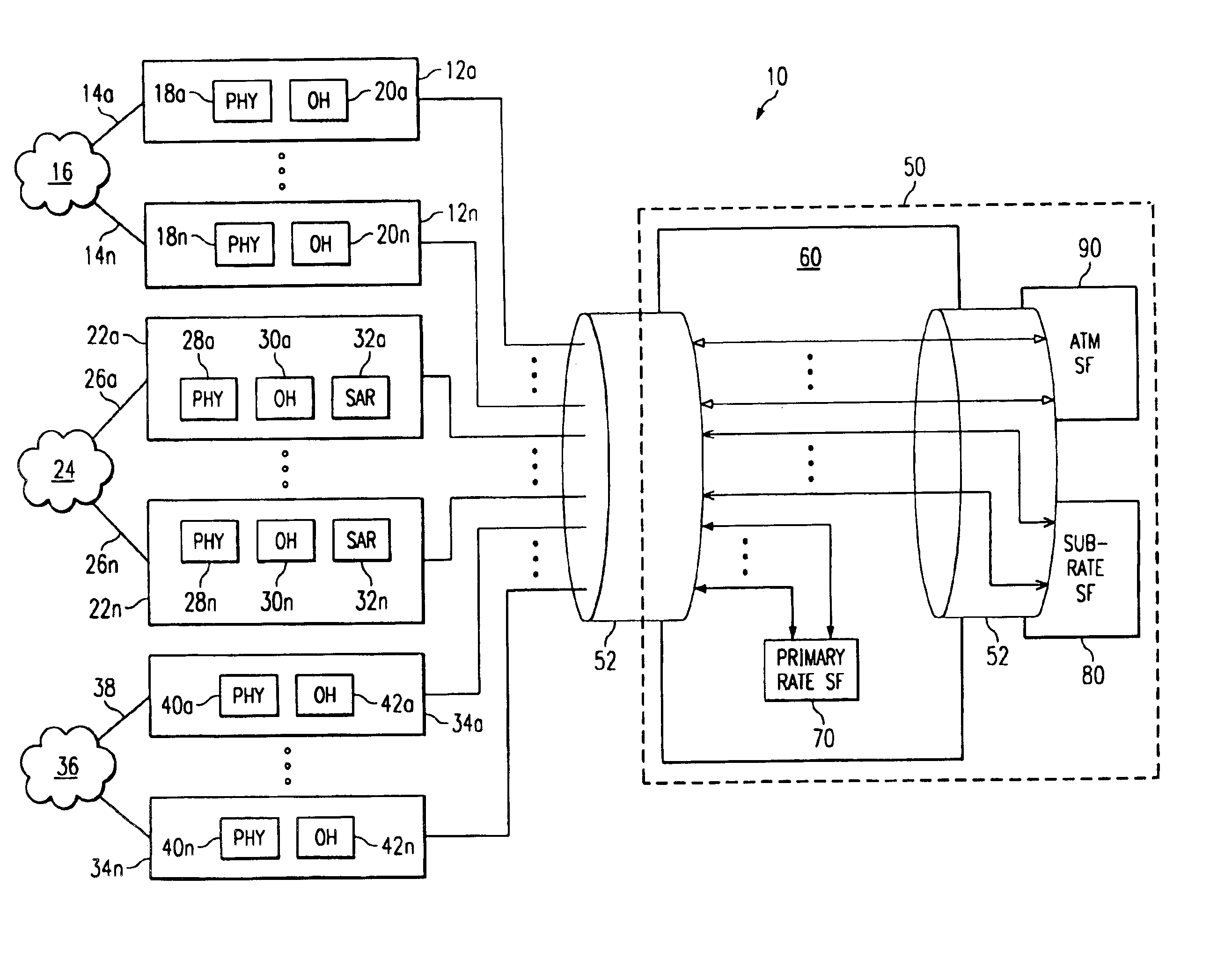
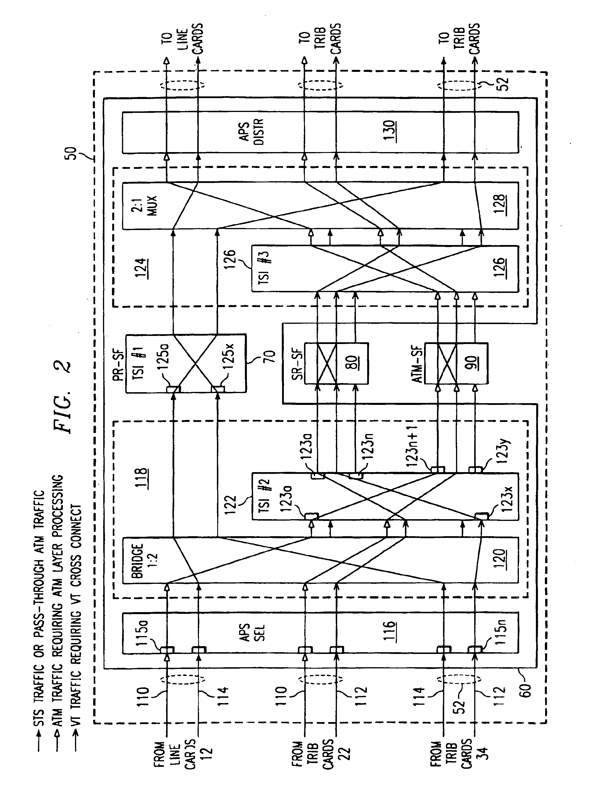
[0005]Technical advantages of the present invention include the provision of a system and method for facilitating transmission of a flexible mixture of various signal types and granularities. In a particular embodiment, the invention facilitates communication of primary rate, sub-rate, and asynchronous transfer mode cell carrying traffic using a single switching complex. Through the invention's unique configuration, sub-rate traffic and asynchronous transfer mode traffic can be processed without affecting the flow of pass-through traffic. In a particular embodiment, the invention provides separate time slot interchanges to handle processing of primary rate signals and sub-rate / asynchronous transfer mode signals.
[0006]The invention can be constructed to have a modular design. For example, the sub-rate switching fabric and the asynchronous transfer mode switching fabric can each reside on a separate physical cards. This design provides an advantage of facilitating interchangability between the switching fabrics. This type of design facilitates customizing bandwidth allocation in the switching complex according to the traffic patterns of any particular application, which facilitates application of the invention to a wide variety of network applications and accommodates changes in network demands as systems evolve.

Problems solved by technology

As communication systems evolve and interface with various network elements, issues arise in handling various signal formats requiring various levels of signal processing.
This approach is expensive, difficult to manage, and generally requires an inordinate amount of space.
A problem with this approach is that mapping time-division multiplexed information onto asynchronous transfer mode traffic generally introduces error-causing jitter into the system.

Method used


Image

  • Switching complex architecture and operation
  • Switching complex architecture and operation
  • Switching complex architecture and operation

Examples


Embodiment Construction

[0012]FIG. 1 is a block diagram of an exemplary system 10 operable to facilitate communication of asynchronous transfer mode (ATM) cells and time-division multiplexed (TDM) information according to the teachings of the present invention. Throughout this description, the terms “asynchronous transfer mode” and “ATM” contemplate not only current versions and standards defining cell transfer techniques, but also other later revisions, modifications, enhancements, or new types of fixed-length and / or variable-length cell transfer technologies.

[0013]System 10 includes a plurality of line cards 12a-12n operable to provide an interface between a switching complex 50 and communication links 14a-14n coupled to a network 16. Throughout this document, the term “coupled” is broad enough to encompass direct or indirect communication between two or more elements said to be “coupled” to one another. The term “coupled” may or may not denote a physical connection between the coupled elements.

[0014]In ...


PUM


Abstract

A system operable to communicate time-division multiplexed information and asynchronous transfer mode cells includes a primary rate switching fabric operable to receive a first plurality of transport signals and to switch the first plurality of transport signals at a first level, a sub-rate switching fabric operable to receive a second plurality of transport signals carrying time-division multiplexed information and to switch the second plurality of transport signals at second level that is a more granular level than the first level, and an asynchronous transfer mode switching fabric operable to receive a third plurality of transport signals carrying asynchronous transfer mode cells, and to switch asynchronous transfer mode cells among the third plurality of transport signals carrying asynchronous transfer mode cells.

Description

BACKGROUND OF THE INVENTION[0001]Typical communication networks may transmit information in one or more signal formats, such as an optical carrier level-n (OC-n) format, an synchronous transport signal level-n format (STS-n), a digital service level-n (DS-n) format, frame relay format or combination of these or other signal formats. In addition these various signal formats may contain, for example, time-division multiplexed information, asynchronous transfer mode cells, or other types of information formats. As communication systems evolve and interface with various network elements, issues arise in handling various signal formats requiring various levels of signal processing.[0002]One approach to addressing these issues is to incorporate separate switching complexes at nodes within the network, each switching complex operable to process a particular signal type or a particular granularity of signal. For example, a network node may include one switching complex operable to process t...

Claims


Application Information

Patent Timeline
IPC IPC(8): H04Q11/04H04L12/56H04L12/64H04M3/00
CPCH04L49/15H04L49/1553H04Q11/0478H04L49/606H04J2203/0012H04L2012/5618H04L2012/641H04L49/254
Inventor CHEN, DAVID X.SHIMBASHI, MASAHIRO
Owner FUJITSU LTD
Learn More