Collapsible storage device with movable closure element

a storage device and movable technology, applied in the field of storage devices, can solve the problems of affecting the use of storage devices, and occupying the available floor space of storage devices, so as to improve the use of storage space within the device, and improve the utility of the devi

Inactive Publication Date: 2005-05-17
SPIN MASTER LTD
View PDF40 Cites 32 Cited by
  • Summary
  • Abstract
  • Description
  • Claims
  • Application Information

AI Technical Summary

Benefits of technology

[0005]The aim of the present invention is to provide improvements to the collapsible storage device which improve the utility of the device and allow improved use of the storage space within the device.

Problems solved by technology

The conventional self standing device, in whichever form, has the disadvantage of becoming part of the furniture of a premises and in many instances the storage device can be unsightly and is required to be accommodated in the premises even when it is not in use.
Furthermore the conventional free standing storage devices are bulky and can encroach onto the available floor area which is particularly noticeable in smaller rooms such as bed rooms, bathrooms and the like.
The devices can also in certain instances represent a hazard, especially to children however they are regarded as being necessary in order to keep articles like toys, clothing and the like in one place.
This therefore means that a substantial area of the available storage space within the device cannot be used as it is required to be left free for the protrusion inwardly of the opening means as, if this space was filled by articles then the opening means will not be able to extend inwardly to the required amount and so the opening means will not function correctly as a funnel.

Method used


Image

  • Collapsible storage device with movable closure element
  • Collapsible storage device with movable closure element
  • Collapsible storage device with movable closure element

Examples


Embodiment Construction

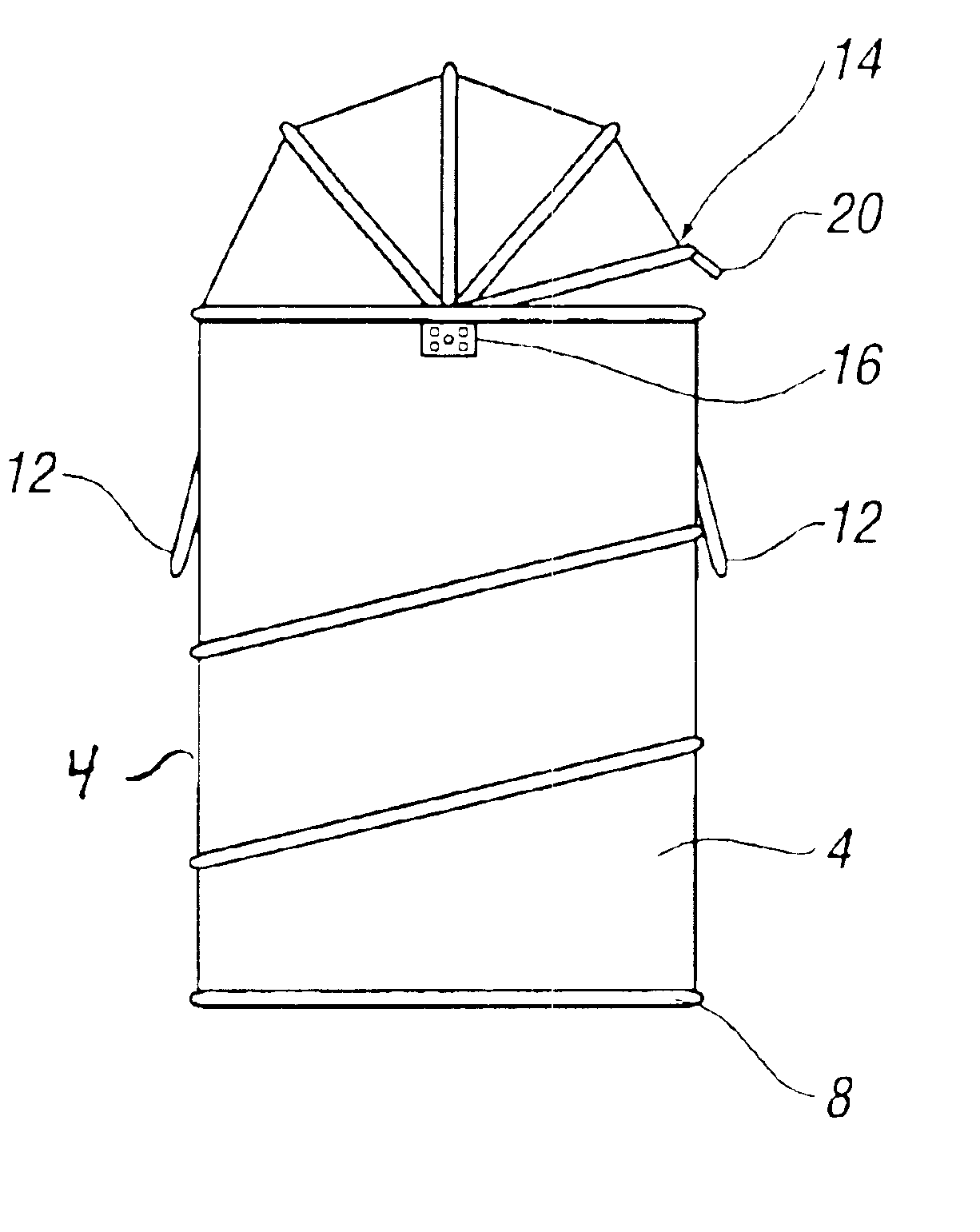
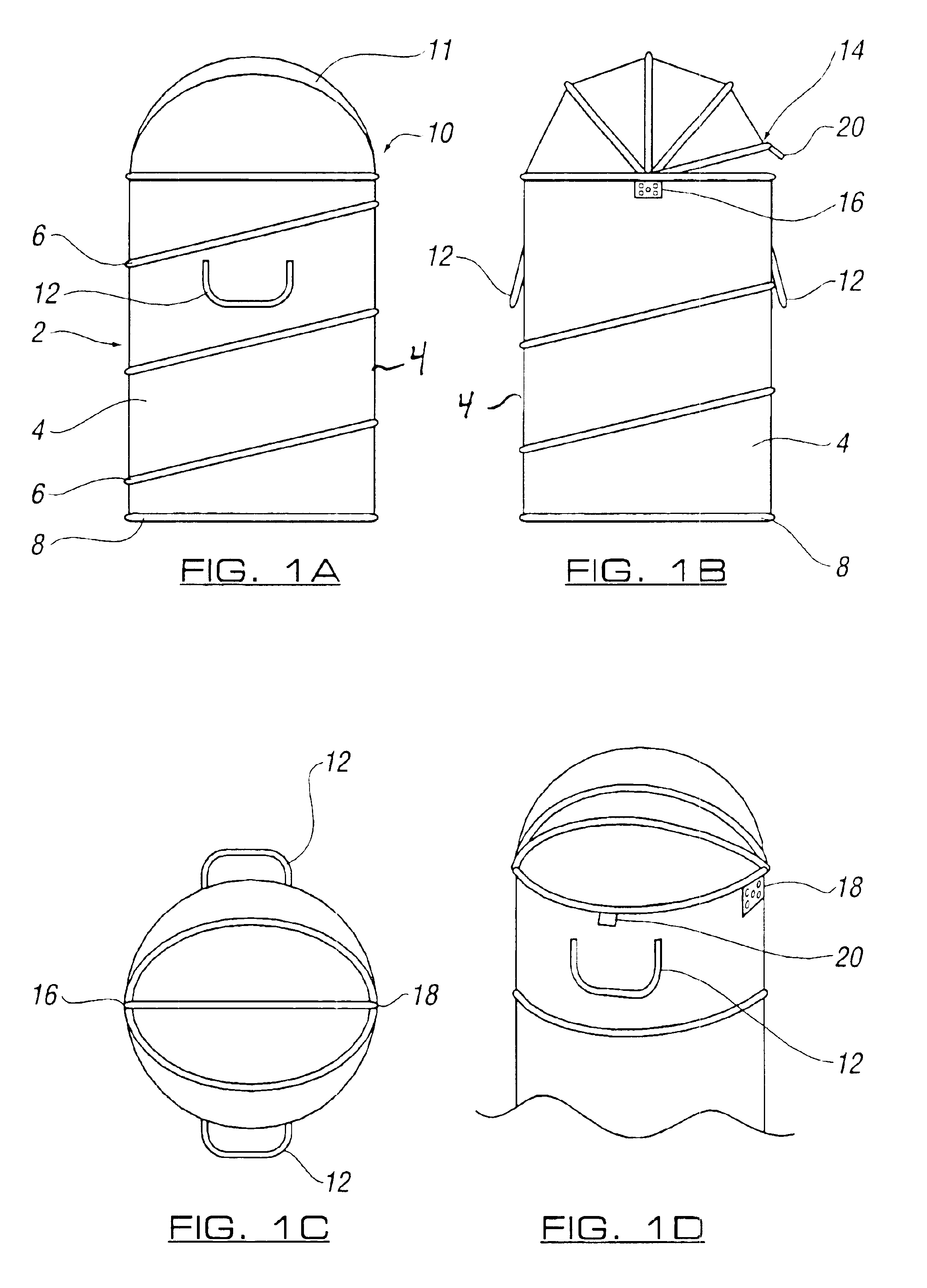
[0034]Referring firstly to FIGS. 1A-1F and 2A-2B, there is illustrated a storage device 2 which comprises side walls 4 in erected condition and which are maintained in the erected condition by a resilient frame means 6. At one end of the side wall 4 there is provided a base portion 8 and at the other end an opening 10 with single closure element 11. Handles 12 are provided on the side walls 4 of the device.

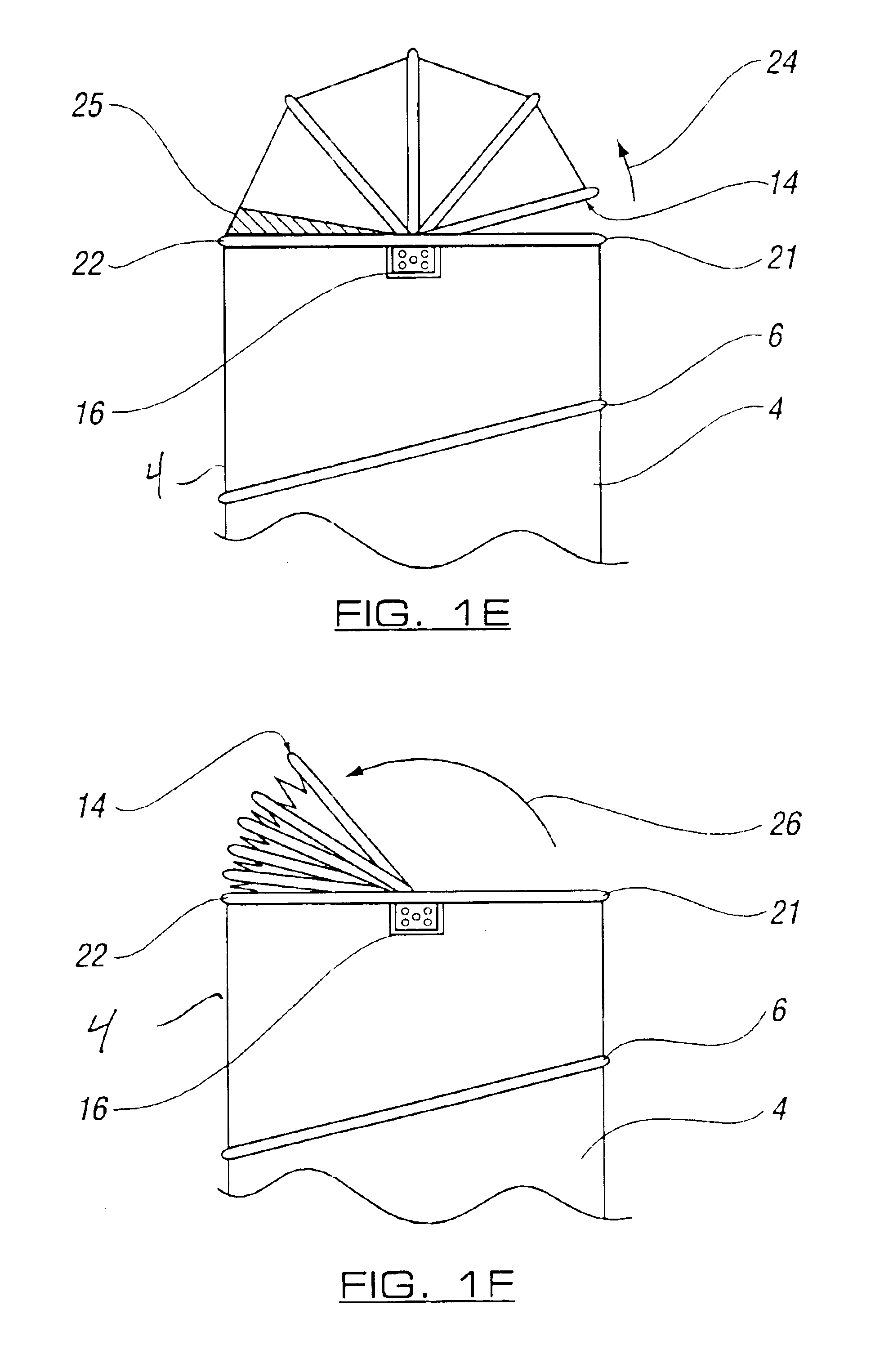
[0035]The closure element 11 is pivotally movable about pivot points 16, 18 on the storage device and forms an inverted bowl shape or dome shape when in a closed position as shown in FIGS. 1A, 1C and 1D. The leading edge 14 of the closure element can be secured to the side walls of the storage device by retaining means 20 as shown.

[0036]To allow access to be gained to the interior of the storage device, the retaining means 20 is released and the leading edge 14 is pivotally moved back from edge 21 to edge 22 as shown by arrows 24, 26 to lie on the peripheral edge 22 of the storage...


PUM


Abstract

A collapsible storage device comprising a resilient frame and sheet material with respect to which the frame is located. The resilient frame and sheet material form the side walls of the device and are movable between a flattened condition and an erected condition to which the resilient frame is biased. At one end of the device there is provided a base and at the other end there is provided an opening. The opening has a single closure element which has a first part attached to one side of the opening and a leading edge which can be moved about a pivotal point between a position at the said one side of the opening so that the storage device is open and a position at or in contact with the other side of the opening to close the opening. The closure element is movable with the storage device between flattened and erected conditions.

Description

CROSS REFERENCE TO RELATED APPLICATIONS[0001]This application is a continuation-in-part (CIP) application of pending U.S. application Ser. No. 09 / 444,755 filed Nov. 22, 1999, now U.S. Pat. No. 6,431,393.BACKGROUND OF THE INVENTION[0002]The invention, which is the subject of this application, relates to a storage device of the sort in which articles such as clothing, toys, sporting articles and the like can be stored and retained in one place.[0003]Conventional storage devices are commonly available and come in many forms such as toy chests, blanket boxes made of wood and storage baskets and containers made of plastics material and are self standing so as to be available for use readily. The conventional self standing device, in whichever form, has the disadvantage of becoming part of the furniture of a premises and in many instances the storage device can be unsightly and is required to be accommodated in the premises even when it is not in use. Furthermore the conventional free sta...

Claims


Application Information

Patent Timeline
Patent Type & Authority Patents(United States)
IPC IPC(8): B65D37/00B65D33/02B65D8/14
CPCB65D37/00B65D33/02
Inventor STEWART, JOHN
Owner SPIN MASTER LTD
Why Eureka
Try Eureka