Male luer lock connector for medical fluid lines

a technology of luer lock and connector, which is applied in the direction of tube connector, catheter, pipe element, etc., can solve the problems of affecting the patient to whom the medical line is applied, affecting the patient's treatment, and affecting the treatment effect of the patient, so as to achieve the effect of reducing the relative drawbacks

a technology of luer lock and connector, which is applied in the direction of tube connector, catheter, pipe element, etc., can solve the problems of affecting the patient to whom the medical line is applied, affecting the patient's treatment, and affecting the treatment effect of the patient, so as to achieve the effect of reducing the relative drawbacks

US6893056B2Inactive Publication Date: 2005-05-17IND BORLA

Image

  • Male luer lock connector for medical fluid lines
  • Male luer lock connector for medical fluid lines
  • Male luer lock connector for medical fluid lines

Examples


Embodiment Construction

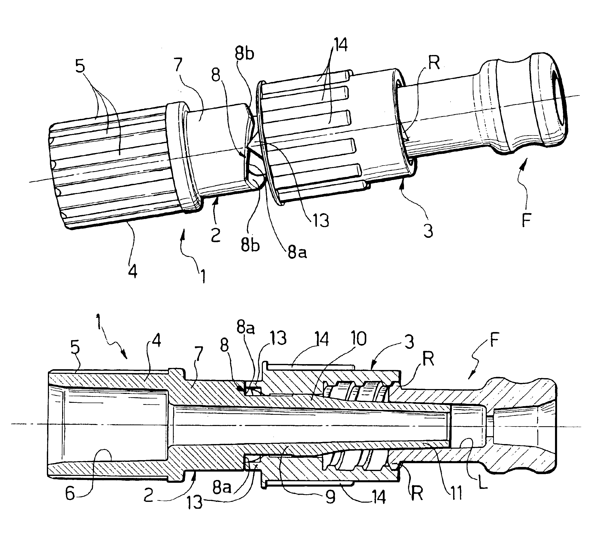
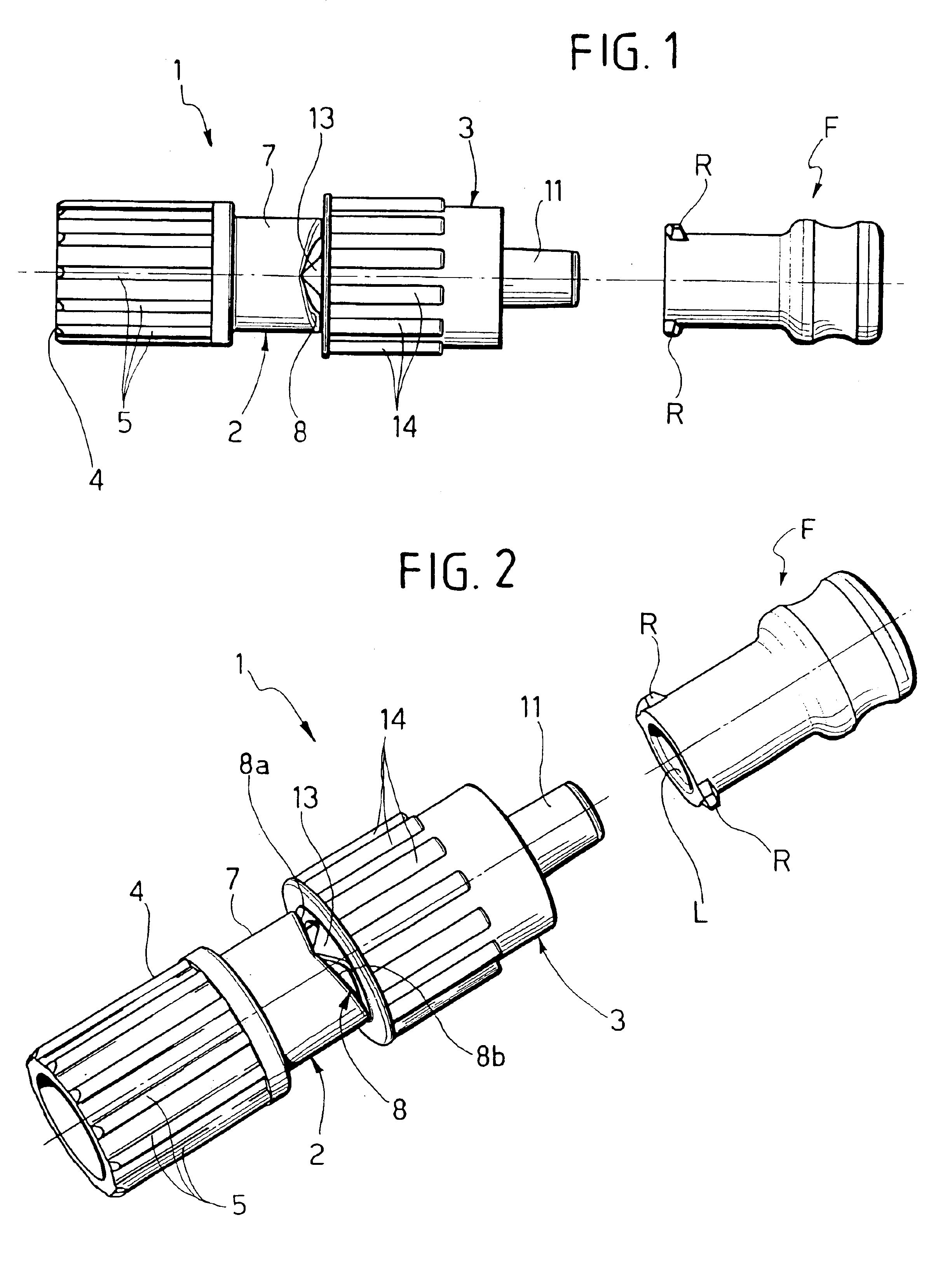
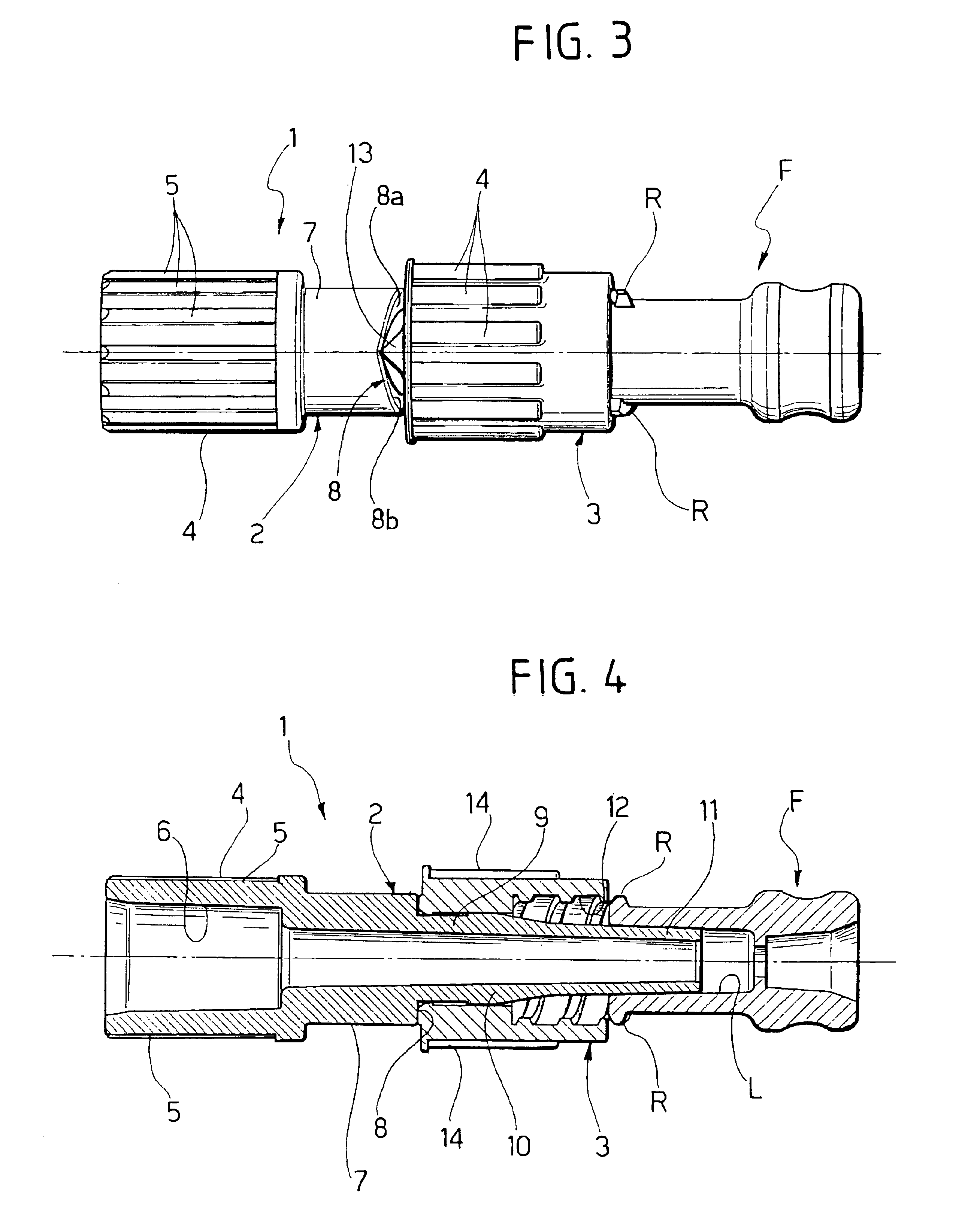
[0021]Firstly with reference to FIGS. 1 and 2, the numeral 1 indicates generically a male luer lock connector according to the invention for medical fluid lines, for example for haemodialysis.

[0022]The male luer lock connector 1 is formed of two components, both of moulded plastic material: an elongated tubular body 2 and an internally threaded bushing 3.

[0023]The elongated tubular body 2 includes, in a single piece, an initial maneuvering part 4 provided with longitudinal gripping projections 5 and the cavity of which, indicated with 6 in FIGS. 4 and 7, is predisposed for connection of the end of a flexible tube not shown in the drawings. The maneuvering part 4 is followed by a cylindrical intermediate part 7 in turn joined, through an annular frontal reaction part indicated generically with 8, to a portion with a cylindrical surface 9 of smaller diameter, visible in FIGS. 4, 5 and 7. The portion with cylindrical external surface 9 connects, through a slightly widened portion 10, t...


PUM

PropertyMeasurementUnit
lengthaaaaaaaaaa
flexibleaaaaaaaaaa
degree of manual forceaaaaaaaaaa

Abstract

A male luer lock connector for medical fluid lines comprising an elongated tubular body having an end portion with external luer cone and an internally threaded bushing mounted so that it can turn and slide on a portion with a cylindrical external surface of the tubular body. The axial backward travel of the bushing allows axial engagement of the male connector with a female luer lock connector even without screwing the bushing, and it is provided with a cam front reaction surface with which the bushing interacts to voluntarily produce axial expulsion of the female luer lock connector.

Description

BACKGROUND OF THE INVENTION[0001]The present invention relates in general to connectors for medical fluid lines, and more specifically regards a male luer lock connector of the type comprising an elongated tubular body having a portion with a cylindrical external surface and an end portion with an external luer cone, and a bushing having an internal thread in which a female luer lock connector can be screwed, the end portion with external luer lock of the tubular body of the male luer lock connector being designed to engage axially with the female luer lock connector.STATE OF THE PRIOR ART[0002]Traditionally, the bushing is fixed in relation to the tubular body of the connector, since it is integral with the portion with the cylindrical external surface of said tubular body. More recently, solutions have been proposed in which the bushing is mounted on the portion with cylindrical external surface of the tubular body in such a way that it can turn and slide for an axial advance trav...

Claims


Application Information

Patent Timeline
17 May 2005
Publication
US6893056B2
IPC
A61M39/10; A61M39/00; F16L47/00; F16L47/04
CPC
F16L47/04; A61M39/1055; A61M39/10; A61M2039/1033
Inventors
GUALA, GIANNI