Paddle-card termination for shielded cable

Inactive Publication Date: 2005-05-17
FCI AMERICAS TECH LLC
View PDF13 Cites 50 Cited by
  • Summary
  • Abstract
  • Description
  • Claims
  • Application Information

AI Technical Summary

Problems solved by technology

Furthermore, computing systems are being interconnected in increasingly complex networks.
Moreover, the ongoing incr

Method used


Image

  • Paddle-card termination for shielded cable
  • Paddle-card termination for shielded cable
  • Paddle-card termination for shielded cable

Examples


Embodiment Construction

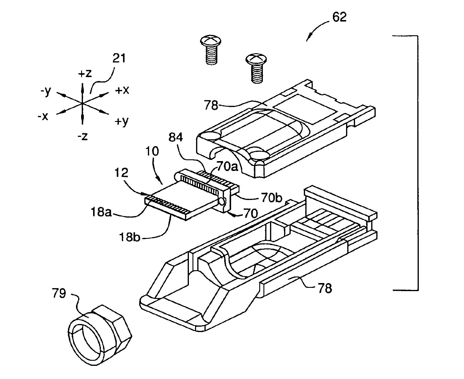
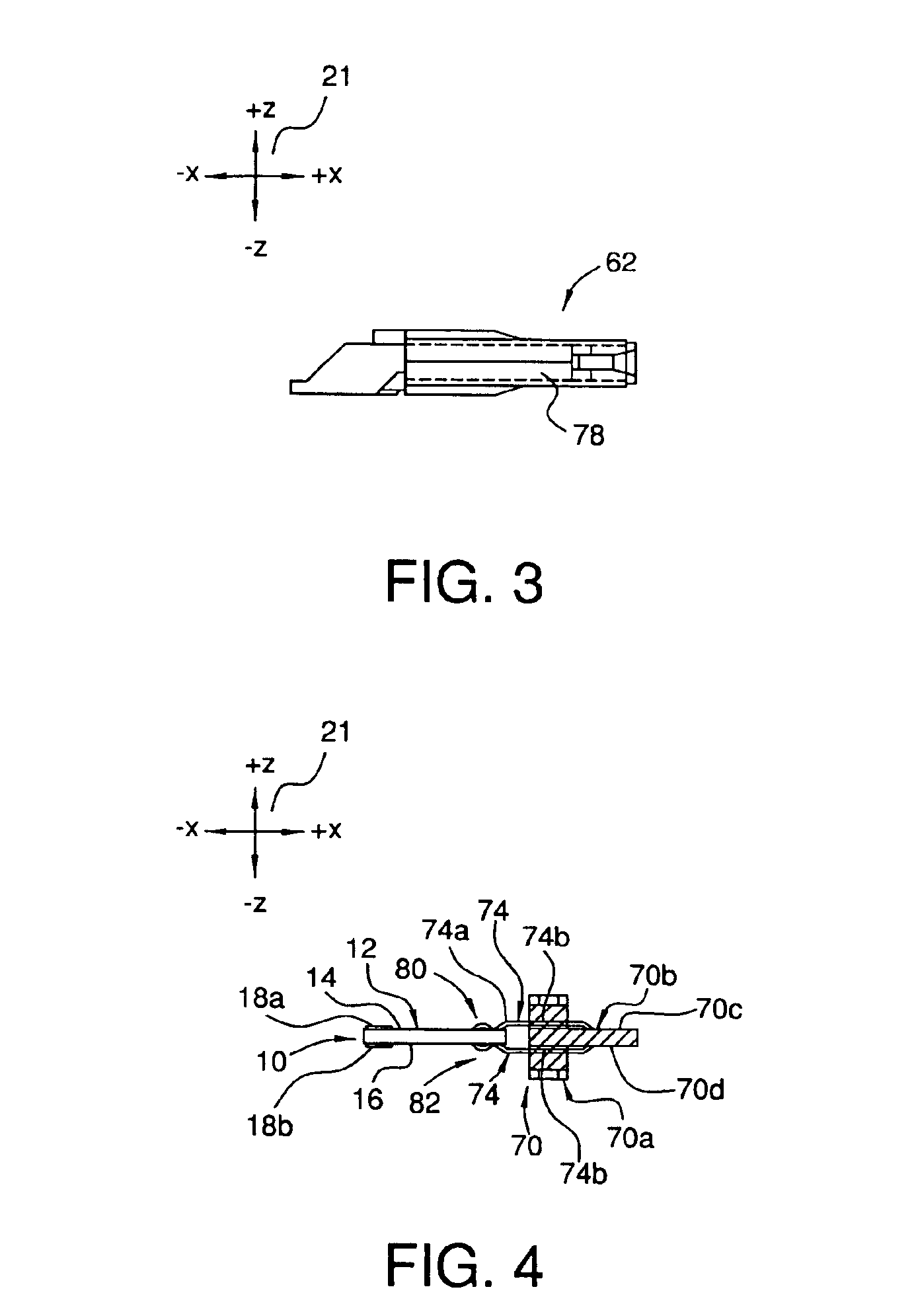
[0033]A connector system comprising a preferred embodiment of a paddle-card cable termination 10 is depicted in FIGS. 1 to 6A. The cable termination 10 terminates a plurality of the shielded cables 11 as generally described above with respect to the conventional paddle-card cable termination 100. The interface between the paddle-card termination 10 and the cables 11 is described in detail below.

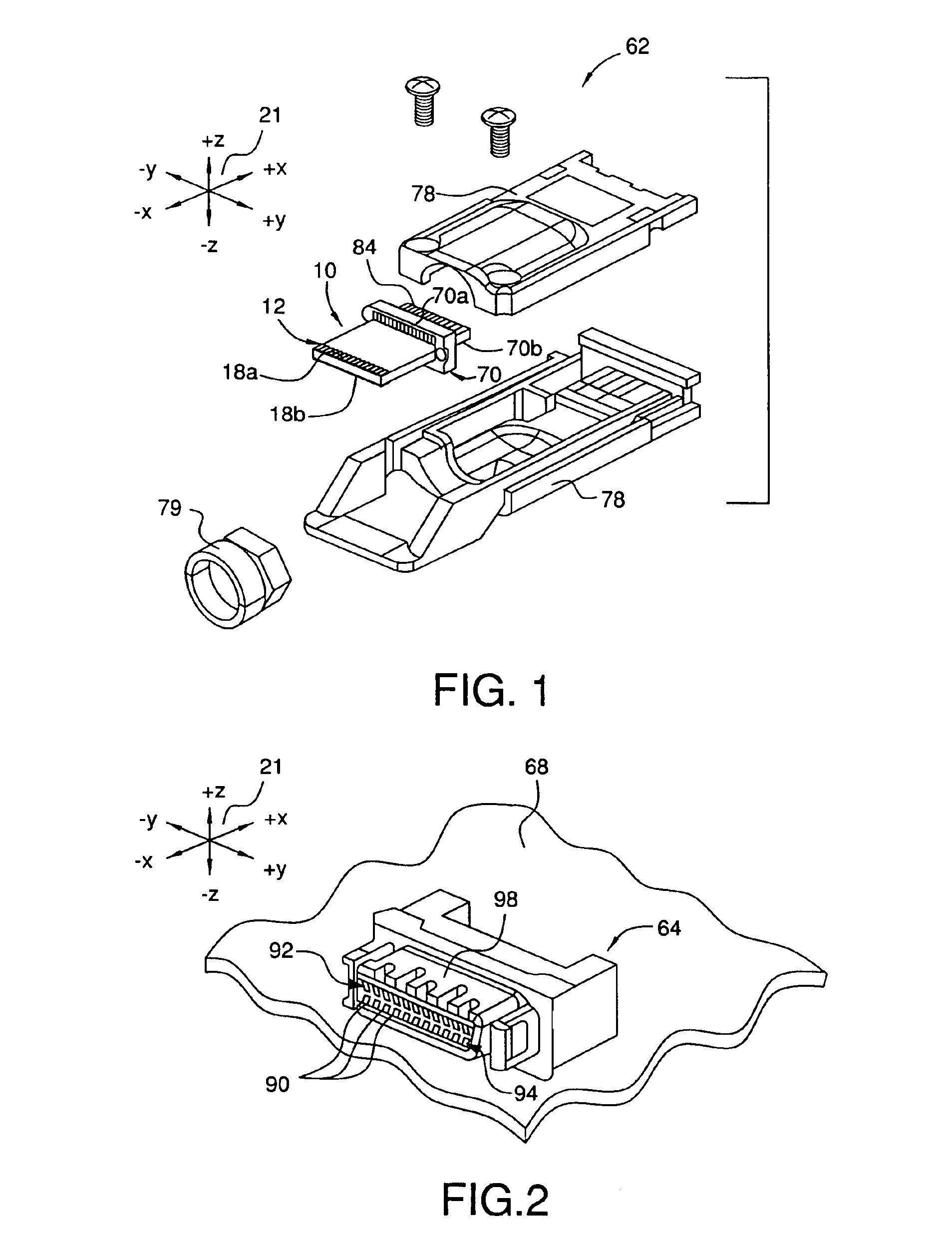
[0034]The paddle-card termination 10 forms part of a plug assembly 62. The plug assembly 62 is adapted to mate with a receptacle 64 having a specific fixed and predetermined vertical pin-out requirement (see FIG. 2). The receptacle 64 is adapted to be mounted on and electrically coupled to a substrate 68. The plug assembly 62 and the receptacle 64 form a connector system for electrically coupling the cable 11 and the substrate 68. The connector system is described in detail for exemplary purposes only, as the preferred embodiment of the cable termination can be used in conjunction with any co...


PUM


Abstract

A preferred embodiment of a cable harness assembly includes a shielded cable comprising a first and a second conductor for conducting a pair of differential signals, and a generally planar board having a first and a second electrically-conductive trace formed thereon and having a first and a second major surface. The first trace is electrically coupled to the first conductor at a first location on the first major surface and extends along the first major surface to a second location on the first major surface. The second trace is electrically coupled to the second conductor at a third location on the first major surface and extends along the first and the second major surfaces to a fourth location on the second major surface.

Description

[0001]This application claims the benefit under 35 U.S.C. §119(e) of U.S. Provisional Patent Application No. 60 / 383,403, which was filed on May 24, 2002 and is hereby incorporated by reference in its entirety.RELATED APPLICATIONS[0002]The present application is related to co-pending U.S. patent application Ser. No. 10 / 391,388, filed Mar. 18, 2003, and co-pending U.S. patent application Ser. No. 10 / 417,521, filed Apr. 17, 2003.FIELD OF THE INVENTION[0003]The present invention relates to electrical connectors and, more particularly, to a paddle-card termination for a shielded electrical cable.BACKGROUND OF THE INVENTION[0004]The speed and capacity of computing systems are constantly on the rise. Furthermore, computing systems are being interconnected in increasingly complex networks. In order to keep pace with these developments, new interconnect systems such as, for example, the InfiniBand architecture have been proposed. The InfiniBand architecture is an industry standard, channel-b...

Claims


Application Information

Patent Timeline
IPC IPC(8): H01R9/03H01R13/648H01R13/658
CPCH01R9/032H01R13/6592H01R13/6594H01R13/6589H01R13/6471H01R9/034H01R13/65912H01R13/65914
Inventor SERCU, STEFAAN
Owner FCI AMERICAS TECH LLC
Why Eureka
Try Eureka