
Method and apparatus for B-mode image banding suppression

Inactive Publication Date: 2005-05-17
GE MEDICAL SYST GLOBAL TECH CO LLC
View PDF12 Cites 1 Cited by
  • Summary
  • Abstract
  • Description
  • Claims
  • Application Information

AI Technical Summary

Benefits of technology

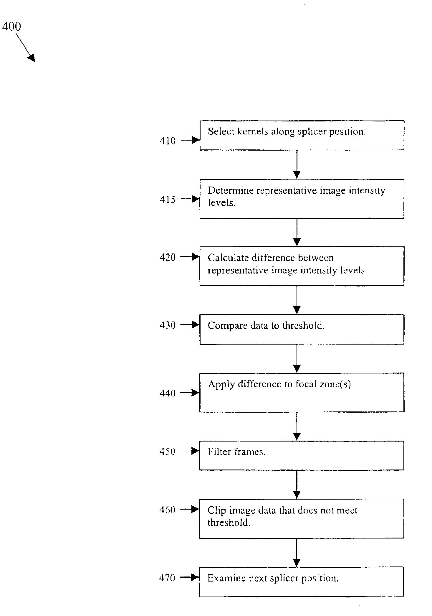
[0010]Certain embodiments include a system and method for banding suppression in a B-mode ultrasound image. Banding occurs in a diagnostic image when two or more focal regions obtained using different waveforms and/or f-numbers, for example, are combined. The difference in image intensity between the focal regions produces banding in a composite image. For purposes of illustration only, the method below will be described with

Problems solved by technology

Poor image quality may prevent reliable analysis of the image.
For example, a decrease in image contrast quality may yield an unreliable image that is not usable clinically.
Differences between different body types may result in blurring, streaking, or introduction of ghost images or artifacts in a resulting image.
However, patient body types are diverse (particularly with pathology), and banding artifacts may occur despite the most carefully selected gain curves.

Method used


Image

  • Method and apparatus for B-mode image banding suppression
  • Method and apparatus for B-mode image banding suppression
  • Method and apparatus for B-mode image banding suppression

Examples


Embodiment Construction

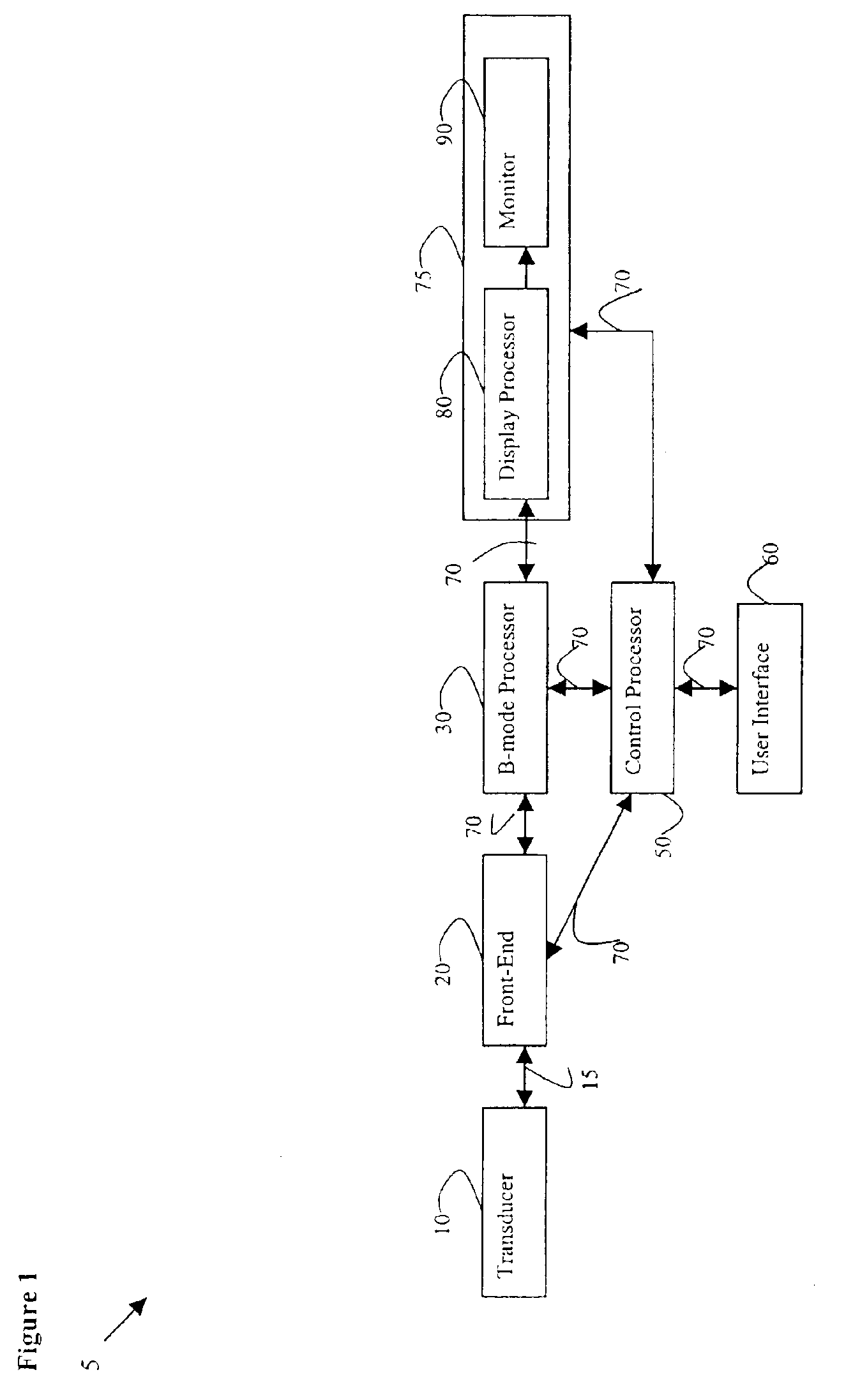
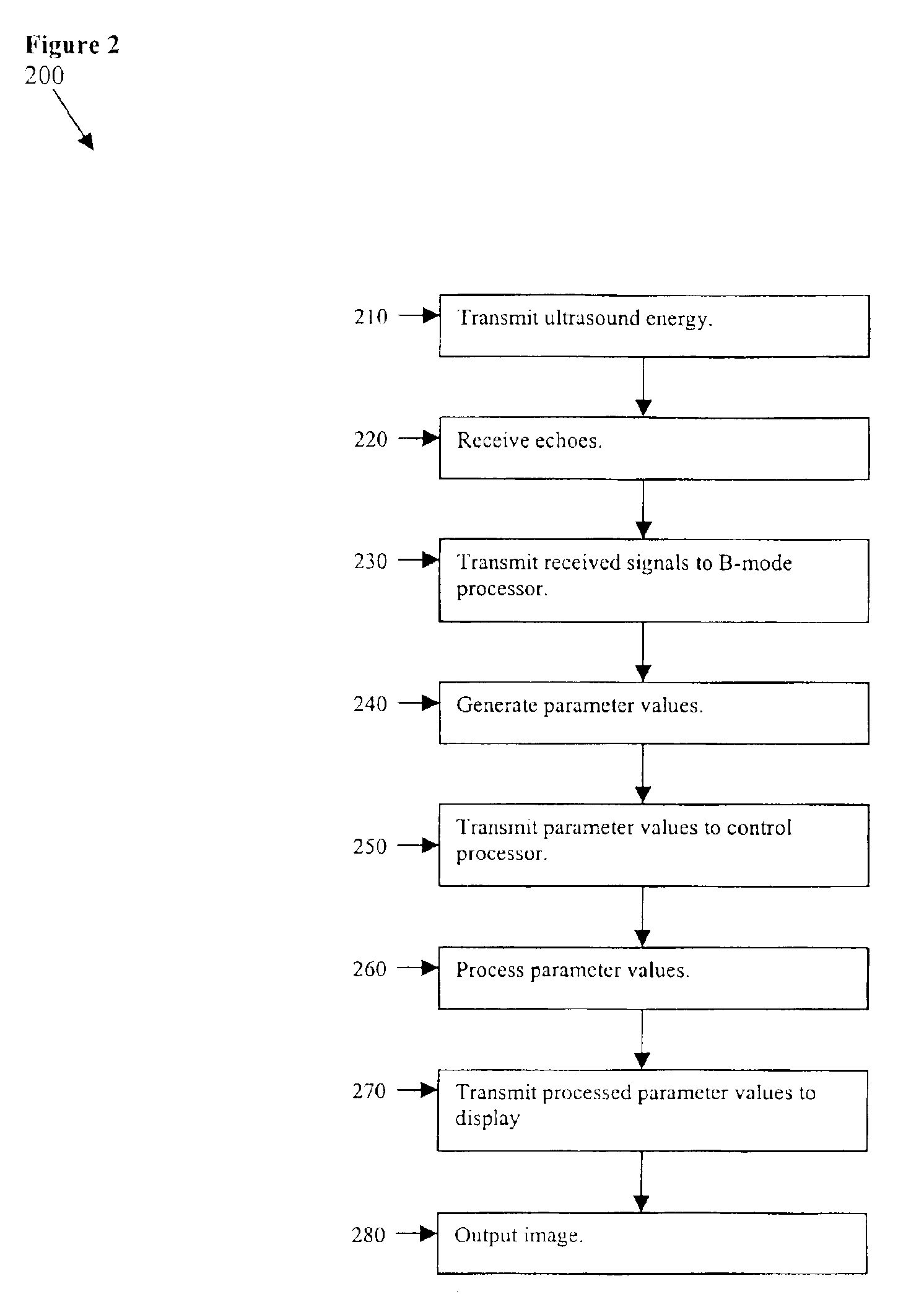
[0022]FIG. 1 illustrates a block diagram of an ultrasound imaging system 5 used in accordance with an embodiment of the present invention. A transducer 10 is used to transmit ultrasound waves into a subject by converting electrical analog signals to ultrasonic energy. The transducer 10 also is used to receive ultrasound waves that are backscattered from the subject by converting ultrasonic energy to analog electrical signals. A front-end 20 including a receiver, a transmitter, and a beamformer, is used to create transmitted waveforms, beam patterns, receiver filtering techniques, and demodulation schemes that are used for various imaging modes. The front-end 20 converts digital data to analog data and vice versa. The front-end 20 interfaces with the transducer 10 via an analog interface 15. The front-end 20 interfaces with a B-mode processor 30 and a control processor 50 via a digital bus 70. The digital bus 70 may include several digital sub-buses. The digital sub-bases may have se...


PUM


Abstract

Certain embodiments include a system and method for banding suppression in a B-mode ultrasound image. Banding occurs in a diagnostic image when two or more focal regions having different waveforms and / or frequencies, for example, are combined. The resulting difference in intensity between the focal regions produces banding in the final image. For purposes of illustration only, the method below will be described with two focal zones. Certain embodiments of the present invention reduce banding in a diagnostic image including a plurality of focal zones by processing the first focal zone, determining intensity around the border or “stitch line” between the two focal regions, and adjusting the second focal region based on the difference in intensity. Preferably, processing is done in real time as image frames are updated.

Description

RELATED APPLICATIONS[0001]The present application relates to, and claims priority from, U.S. Provisional Application No. 60 / 423,076 filed on Nov. 1, 2002, and entitled “Method and Apparatus for B-Mode Image Banding Suppression”.FEDERALLY SPONSORED RESEARCH OR DEVELOPMENT[0002][Not Applicable]MICROFICHE / COPYRIGHT REFERENCE[0003][Not Applicable]BACKGROUND OF THE INVENTION[0004]The present invention generally relates to ultrasound imaging. In particular, the present invention relates to banding suppression in ultrasound imaging.[0005]Ultrasound is sound having a frequency that is higher than a normal person may hear. Ultrasound imaging utilizes ultrasound waves or vibrations in the frequency spectrum above normal human hearing, such as the 2.5-MHz range. Ultrasound imaging systems transmit ultrasound into a subject, such as a patient, in short bursts. Echoes are reflected back to the system from the subject. Diagnostic images may be produced from the echoes. Ultrasound imaging techniqu...

Claims


Application Information

Patent Timeline
IPC IPC(8): G01S7/52A61B8/14A61B8/00
CPCG01S7/52046A61B8/14
Inventor PANDA, SATCHIDONG, FANG F.CHIAO, RICHARD Y.CHILUKURI, SASTRY V. S.
Owner GE MEDICAL SYST GLOBAL TECH CO LLC
Learn More