Method and device for cutting a flat workpiece that consists of a brittle material

a flat workpiece and material technology, applied in the direction of stone-like material working apparatus, glass making apparatus, laser beam welding apparatus, etc., can solve the problems of reduced mechanical durability, increased danger of breakage, and relatively long duration of forming the score, so as to reduce the time of cutting process and reduce the danger of damaging the brittle material

Inactive Publication Date: 2005-05-17
SCHOTT AG
View PDF9 Cites 31 Cited by
  • Summary
  • Abstract
  • Description
  • Claims
  • Application Information

AI Technical Summary

Benefits of technology

[0012]The invention has the task to carry out the initially-mentioned method and to configure the initially-mentioned arrangement in such a manner that the times for the cutting process are reduced and the danger of damaging the brittle material is very low.

Problems solved by technology

It is disadvantageous with this method that particles (splinters) are separated from the surface by scoring which can then deposit on the glass and there, for example, lead to scratches.
Furthermore, the microtears in the cut edge, which arise when scoring, lead to a reduced mechanical durability, that is, to an increased danger of breakage.
The disadvantages of the known method are:
Furthermore, the duration of forming the score is relatively long so that the problem of damage of the glass with the formation of splinters arises.

Method used


Image

  • Method and device for cutting a flat workpiece that consists of a brittle material
  • Method and device for cutting a flat workpiece that consists of a brittle material

Examples


Embodiment Construction

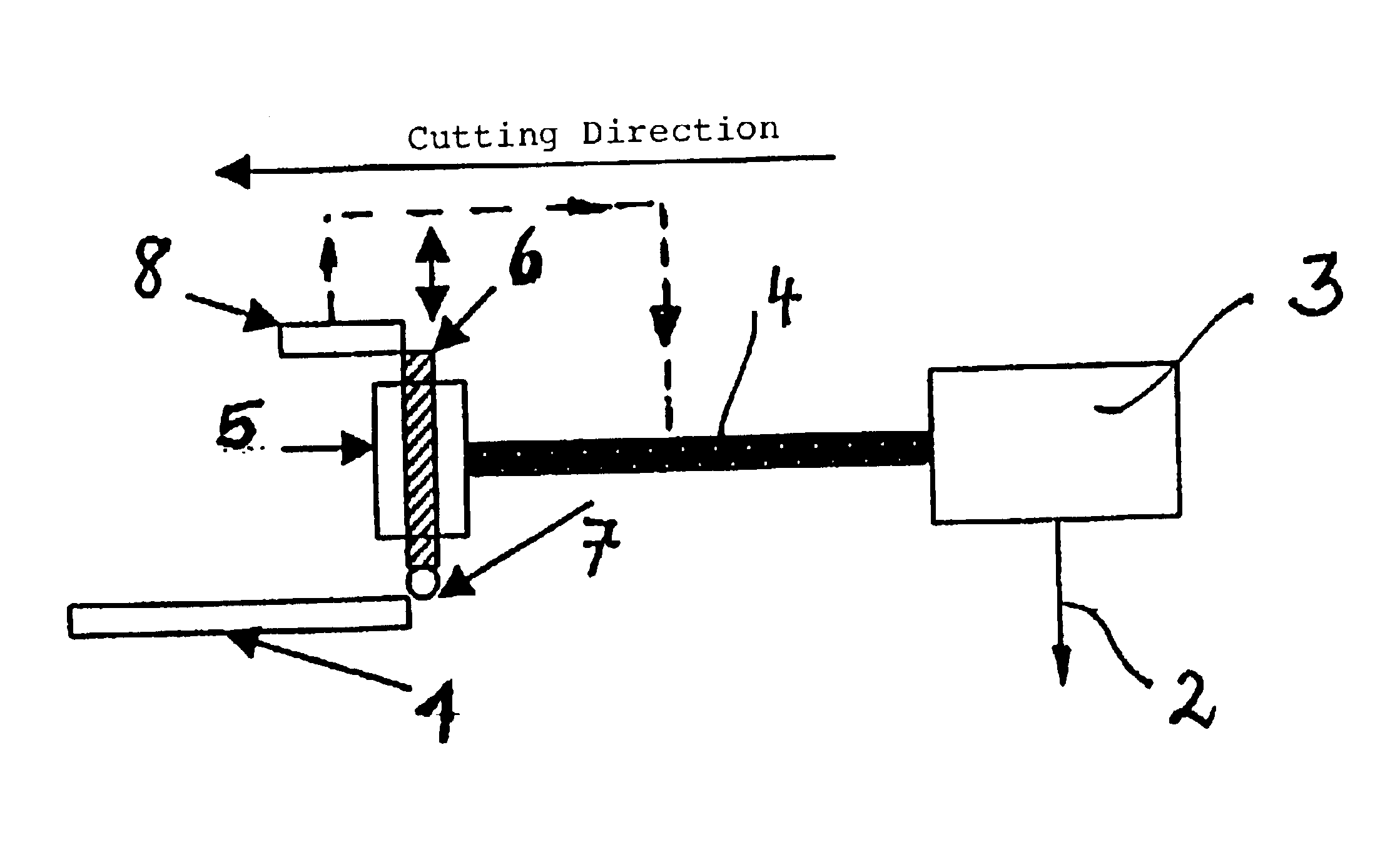
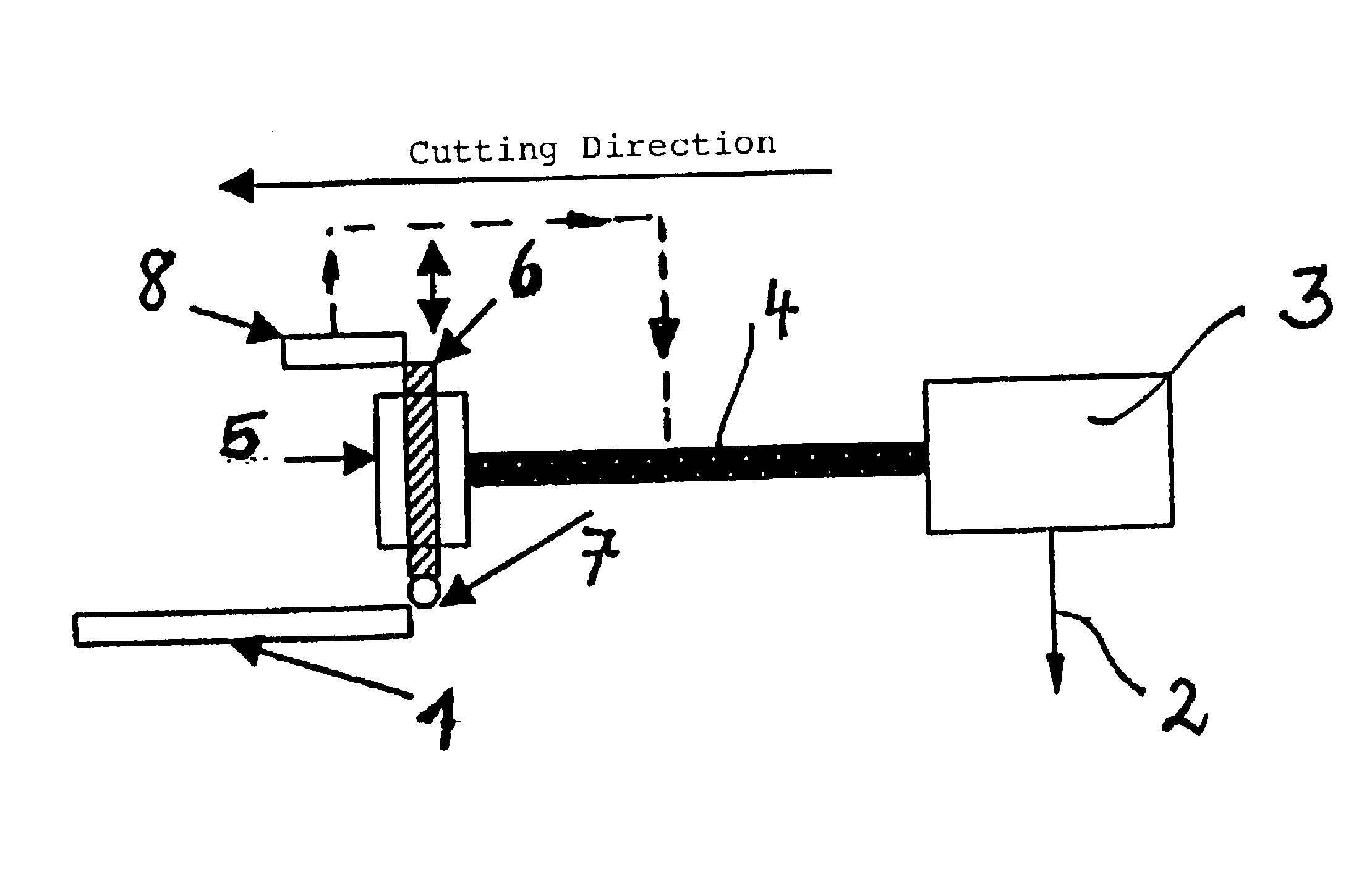
[0021]A flat glass substrate 1 is to be cut by a laser beam 2 of a laser scanner 3 along a pregiven cutting line.

[0022]The corresponding arrangements are known, for example, from the publications mentioned initially herein and therefore do not have to be explained here further. A relative movement is present between the laser beam 2 and the glass substrate 1 along the given cutting direction. Typically, the glass substrate is fixed in position and the laser beam 2 is moved. Conversely, the laser beam 2 can be fixed and the glass substrate 2 moved.

[0023]A solenoid 5 is connected to the scanner 3 in a controlling manner via the symbolically shown connection 4. The solenoid 5 has a switching flag 6 which can be moved upwardly or downwardly as indicated by arrows in dependence upon the drive of the solenoid 5. A scoring tool 7 is mounted at the lower end of the switching flag 6 facing the glass substrate and is, for example, a hard metal wheel. A position sensor 8 is assigned to the swi...


PUM

PropertyMeasurementUnit
time intervalaaaaaaaaaa
brittleaaaaaaaaaa
stroke distanceaaaaaaaaaa

Abstract

An arrangement for cutting a flat workpiece includes a drive unit for generating a relative movement between the focused laser beam (2) and the workpiece (1). The laser beam induces a thermomechanical stress in the workpiece along the cutting line. A scoring tool (7) generates an initial score at the start of the cutting line. A “flying” scoring is provided wherein a unit (5, 6, 8) moves the scoring tool (7). The unit is coupled in a controlled manner to the cutting movement of the laser beam (2) so that the scoring tool (7) can be brought into a short-time scoring working engagement with the workpiece (1) at the start of the cutting movement.

Description

FIELD OF THE INVENTION[0001]The invention relates to a method for cutting a flat workpiece made of brittle material, especially, glass or ceramic, with a laser beam by generating a relative movement between the laser beam and the flat workpiece while moving the laser beam along a pregiven cutting line with induction of a thermomechanical tension proceeding from a mechanically generated initial score. A preferred application is the cutting of flatBACKGROUND OF THE INVENTION[0002]The invention relates further to an arrangement for cutting such a flat workpiece by means of a laser beam.[0003]Conventional separation methods for flat glass are based on first generating a score in the glass utilizing a diamond or a cutting wheel in order to thereafter break the glass along the weakened location generated in this manner by an external mechanical force. It is disadvantageous with this method that particles (splinters) are separated from the surface by scoring which can then deposit on the g...

Claims


Application Information

Patent Timeline
Patent Type & Authority Patents(United States)
IPC IPC(8): C03B33/09C03B33/00B28D1/28B23K26/00B23K26/40C04B41/91
CPCC03B33/091C03B33/09
Inventor HAUER, DIRKGEISSLER, HEINZ-GEORG
Owner SCHOTT AG
Why Eureka
Try Eureka