Disk drive which detects head flying height using first and second non-overlapping data patterns with different frequencies

a data pattern and head flying technology, applied in the direction of recording information storage, maintaining head carrier alignment, instruments, etc., can solve the problem of unreadable written data, and achieve the effect of increasing disk access times

Inactive Publication Date: 2005-05-17
SEAGATE TECH HDD HLDG +3
View PDF11 Cites 60 Cited by
  • Summary
  • Abstract
  • Description
  • Claims
  • Application Information

AI Technical Summary

Benefits of technology

[0006]The present invention relates to a system for determining whether the actual flying height of a head is within a desired range. The system is capable of operating “on the fly” and may therefore be implemented in a disk drive system without substantially increasing disk access times. That is, the flying height determination can be made substantially in real time, before the head reaches the data sector to be written to or read from. This allows the drive to forego the transfer of data between the head and the disk when it is found that the head is outside of the desired flying height range, which is generally determined by empirical methods. The present invention has application in virtually any type of data recording system using either a contact, a pseudo contact, or a non-contact head to transfer data from / to a moving medium. This can include, for example, magnetic disk drive systems, magnetic tape systems, and optical disk drive systems. In one application, the invention is used in a system utilizing low flying height heads, such as the Tripad™ head manufactured by Read-Rite.
[0008]In one aspect of the present invention, a disk drive is provided that comprises a disk having a first data pattern with a first frequency and a second data pattern with a second, higher frequency on a first track. The disk drive also includes means for reading the first and second data patterns, using a head at a first vertical distance from the disk, to create first and second analog signal portions, respectively. In addition, the disk drive includes a determination unit for determining whether the first vertical distance of the head is within an acceptable range for performing a transfer of user data between the first track and an exterior environment using the first analog signal portion and the second analog signal portion, wherein the determination unit does not require the movement of the head to a substantially different vertical distance to make the determination.

Problems solved by technology

This is particularly the case during write operations where an unexpected increase in flying height can result in written data that is unreadable.

Method used


Image

  • Disk drive which detects head flying height using first and second non-overlapping data patterns with different frequencies
  • Disk drive which detects head flying height using first and second non-overlapping data patterns with different frequencies
  • Disk drive which detects head flying height using first and second non-overlapping data patterns with different frequencies

Examples


Embodiment Construction

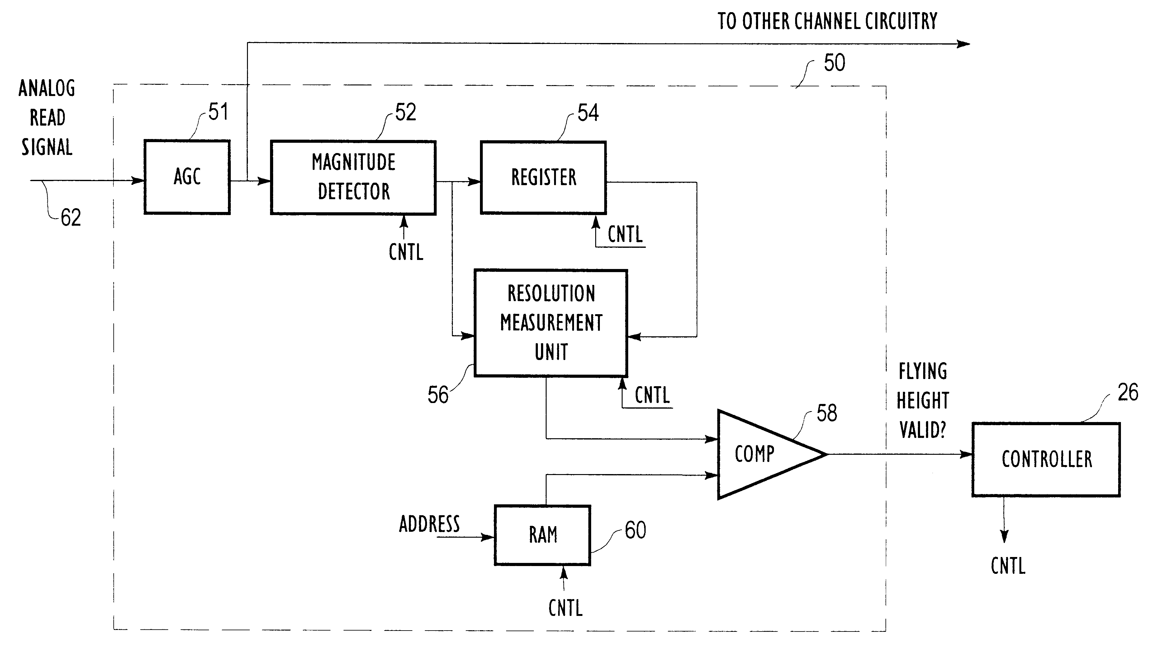
[0029]The present invention relates to a system for detecting head flying height variations in a disk drive in real time. That is, the system allows head flying height to be checked on the fly while a corresponding read or write operation is being performed. In this way, read and / or write operations can be postponed whenever it is determined that the current flying height of the head is outside a normal flying height range. Although the system may be used in virtually any type of data recording system that uses a head to read / write information to a recording medium, the system is of particular value in systems that use low flying height head elements, where even small variations in flying height can degrade performance significantly. As used herein, the term low flying height head encompasses both contact heads and pseudo-contact heads.

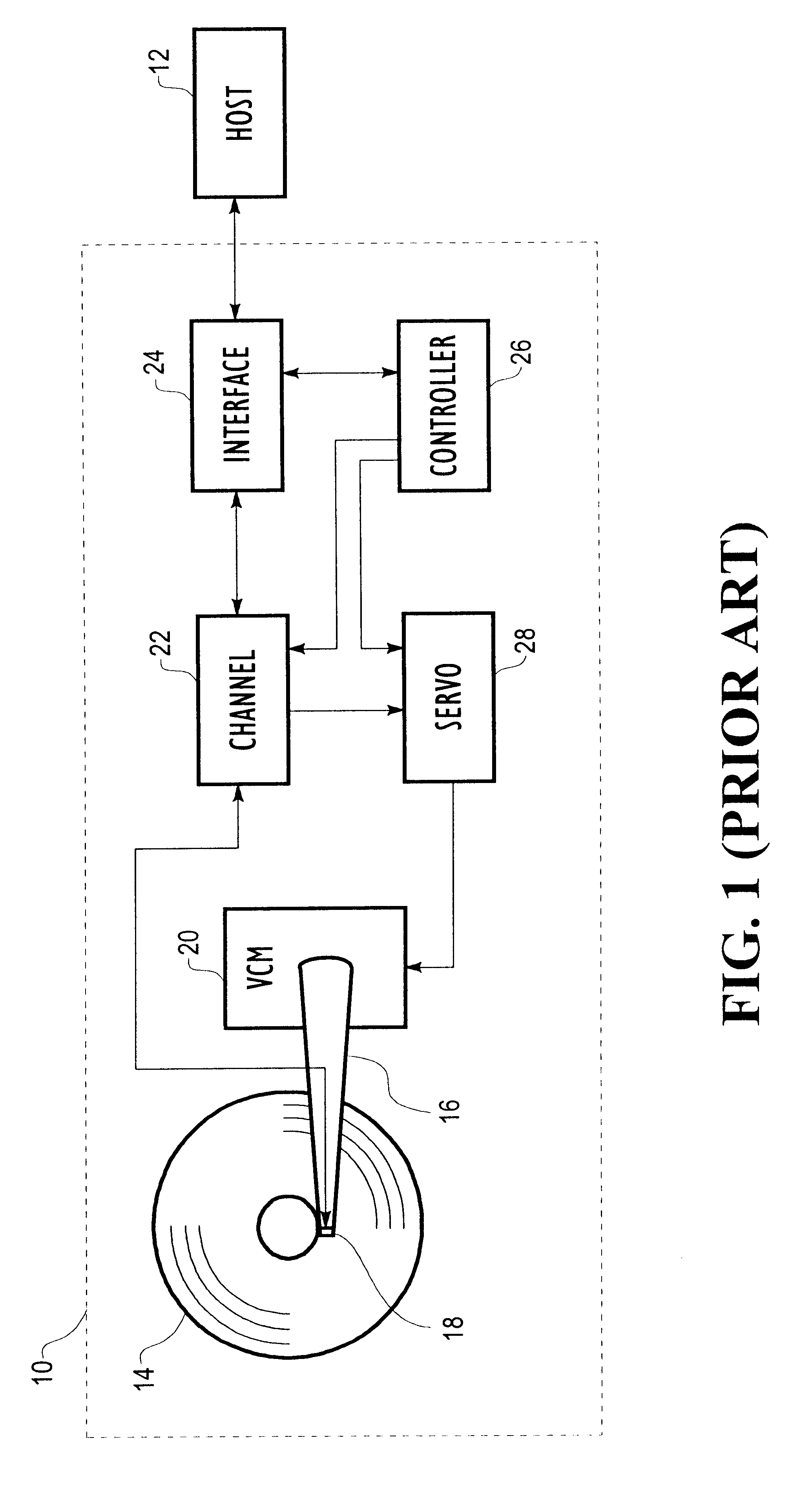
[0030]FIG. 1 is a block diagram of a disk drive system 10 which can utilize features of the present invention. As illustrated, the disk drive system ...


PUM

PropertyMeasurementUnit
frequencyaaaaaaaaaa
flying heightaaaaaaaaaa
distanceaaaaaaaaaa

Abstract

The present invention relates to a system for determining whether the flying height of a read / write head above a disk in a disk drive is within an acceptable range, in substantially real time. The system relies on variations in read signal resolution with flying height to make the determination. In one embodiment, read signal resolution is measured and compared to a predetermined threshold value to determine whether the present flying height is in the desired range. In another embodiment, the number of peaks in a read signal that are detected (and / or not detected) by a detector is used to determine whether the head is in the proper flying height range. Because of read signal resolution effects, the number of detected peaks will decrease as the flying height of the head is increased. Means are also provided for postponing a transfer of data to / from the disk when it is determined that the head is not within the acceptable range.

Description

[0001]This application is a divisional of U.S. application Ser. No. 09 / 224,202, filed Dec. 30, 1998, which is a continuation of U.S. application Ser. No. 08 / 764,340, filed Dec. 12, 1996 (U.S. Pat. No. 5,909,330).FIELD OF THE INVENTION[0002]The invention relates in general to digital data storage devices and, more particularly, to digital data storage devices that utilize a head to transfer data from / to a moving medium.BACKGROUND OF THE INVENTION[0003]A disk drive is a digital data storage device that stores data in substantially concentric tracks on the surface of a disk. During the operation of a disk drive, the disk is rotated at a substantially constant rate while data is written to or read from its surface. The disk drive is generally coupled to a host computer that delivers access requests to the disk drive whenever the host desires to store or retrieve digital information. To perform an access request, the disk drive first positions a head above the track of the rotating disk ...

Claims


Application Information

Patent Timeline
Patent Type & Authority Patents(United States)
IPC IPC(8): G11B17/32G11B5/60
CPCG11B17/32G11B5/6005G11B5/6029
Inventor CARLSON, LANCE R.WHALEY, JEFFREY L.METZ, ROBERT L.
Owner SEAGATE TECH HDD HLDG
Why Eureka
Try Eureka