Apparatus and method for collecting light

a technology of light collection and light collection, which is applied in the direction of lighting and heating apparatus, instruments, optical elements, etc., can solve the problems of large environmental pollution, insufficient complete solution, and many do not provide a complete solution

Inactive Publication Date: 2005-05-17
HO EDWARD
View PDF10 Cites 60 Cited by
  • Summary
  • Abstract
  • Description
  • Claims
  • Application Information

AI Technical Summary

Benefits of technology

[0022]The invention accordingly comprises the several steps and the relation of one or more of such steps with respect to each of the others, and the apparatus embodying features of construction, combination(s) of elements and arrangement of parts that are adapted to effect such steps, all as exemplified in the following detailed disclosure, and the scope of the invention may be indicated in the claims.

Problems solved by technology

“Traditional” energy sources, such as oil and natural gas, continue to be depleted, and the use of such energy sources has caused a significant amount of pollution to the environment.
Although many of these alternatives address some of the problems with “traditional” energy sources, most do not provide a complete solution.
But it presents immense environment concerns.
Hydro power plants provide energy with essentially no air pollution, but otherwise alter entire local ecosystems.
However, there has not been an adequately efficiency method of collecting and utilizing this energy source.
None of these patents, however, discloses or suggests a light collection method and apparatus that is a sufficiently consistent and reliable source for providing electrical power to be adaptable to a traditional power system for electrical power.

Method used


Image

  • Apparatus and method for collecting light
  • Apparatus and method for collecting light
  • Apparatus and method for collecting light

Examples


Embodiment Construction

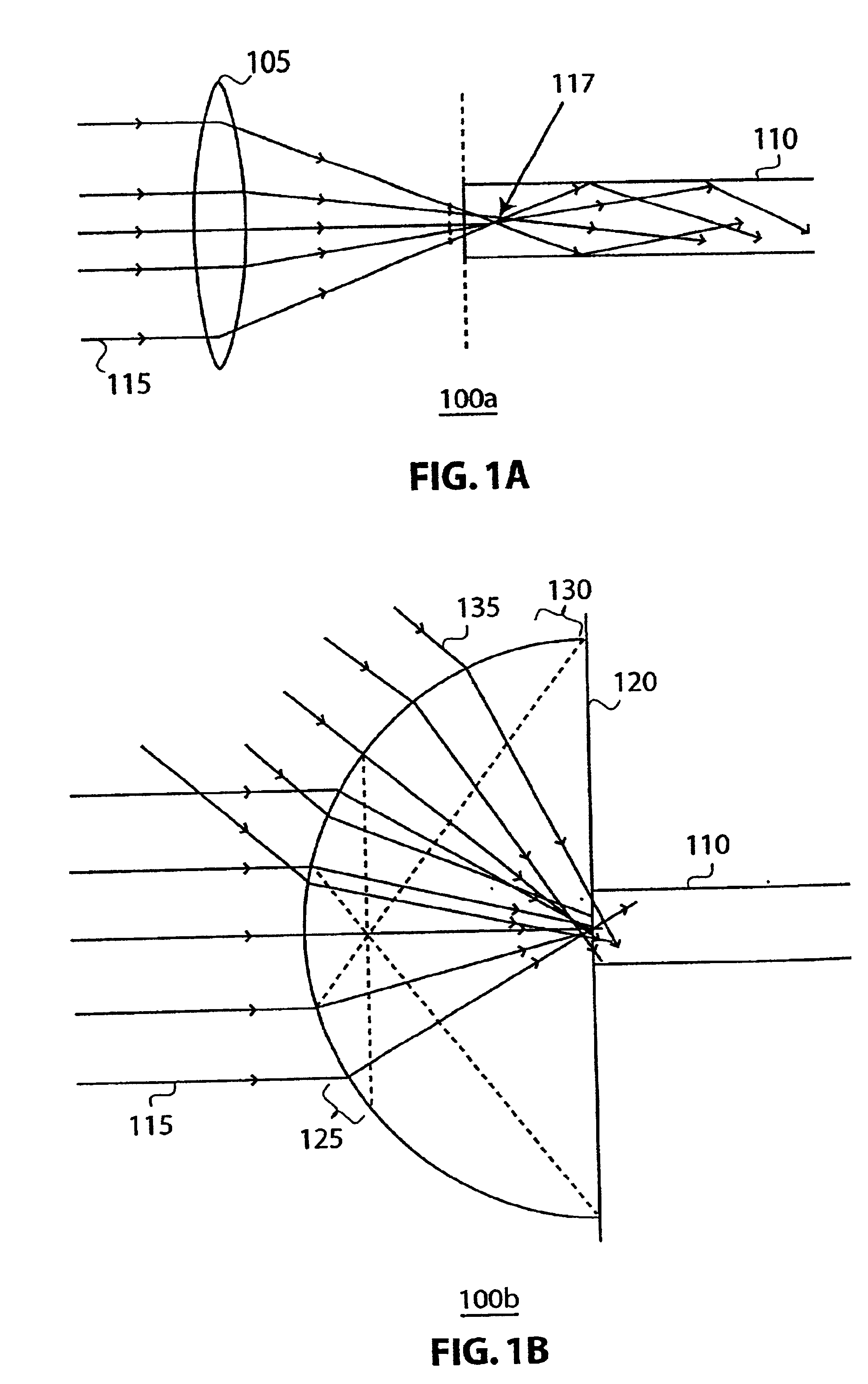
[0053]FIGS. 1A and 1B illustrate light collection by directing incoming light into an optical fiber, which may then transmit the collected light to an energy transfer, according to respective embodiments of the invention. As shown in FIG. 1A, a light collection system 100a may include a convex lens 105 and an optical fiber 110. For a distant light source (e.g. the sun), incoming light 115 passing through convex lens 105 is bent inward, or made to converge, to a focal point 117 of lens 105 (the place where light rays 115 converge). Lens 105 may be made from a number of transparent materials, each with a corresponding index of refraction (denoted by the variable n). For example, acrylic has an index of refraction of 1.49 (n=1.49) and Pyrex glass has an index of refraction of 1.39 (n=1.39). Optical fiber 110 may be placed at or near focal point 117 of lens 105 for collecting the converged light.

[0054]Optical fiber 110 may be any light transmission medium that preserves the energy level...


PUM


Abstract

A spherical lens is used to focus and direct light into an optical fiber for transmitting the focused light to an energy converter, a lighting or heating system, or a lighting or heating apparatus. The collected light may be converted to electricity by powering a steam turbine generator, thermal photo-voltaic cells, or the like. The collect light may also be supplied as a centralized light source to reflective lighting fixtures connected by fiber optics.

Description

FIELD OF THE INVENTION[0001]The present invention relates to a light collection apparatus and method that utilizes a number of light collectors each having a spherical surface, optical fibers for directing the collected light to an energy transfer or a number of lighting fixtures, and retractable pivoting connectors for connecting the light collectors to the optical fibers. The energy transfer may transfer the collected energy to power a steam turbine of an electrical power generator.[0002]Each of the applications and patents cited in this text, as well as each document or reference cited in each of the applications and patents (including during the prosecution of each issued patent; “application cited documents”), and each of the PCT and foreign applications or patents corresponding to and / or claiming priority from any of these applications and patents, and each of the documents cited or referenced in each of the application cited documents, are hereby expressly incorporated herein...

Claims


Application Information

Patent Timeline
Patent Type & Authority Patents(United States)
IPC IPC(8): F24J2/08F24J2/06G02B6/42F24S23/00F24S23/30
CPCF24J2/067F24J2/08G02B6/4298H01L31/0547H01L31/0543Y02E10/52Y02E10/40F24S23/12F24S23/30
Inventor HO, EDWARD
Owner HO EDWARD
Why Eureka
Try Eureka