
Locating a source of emanations

a technology of emanations and source, applied in the direction of seismology, instruments, and seismology for waterlogging, can solve the problem of laborious setup of devices needed to carry out open-path measurements

Inactive Publication Date: 2005-05-17
SHELL USA INC
View PDF7 Cites 35 Cited by
  • Summary
  • Abstract
  • Description
  • Claims
  • Application Information

AI Technical Summary

Problems solved by technology

A disadvantage of the known method is that it is laborious to set up the devices needed to carry out the open-path measurements.

Method used


Image

  • Locating a source of emanations
  • Locating a source of emanations

Examples


Embodiment Construction

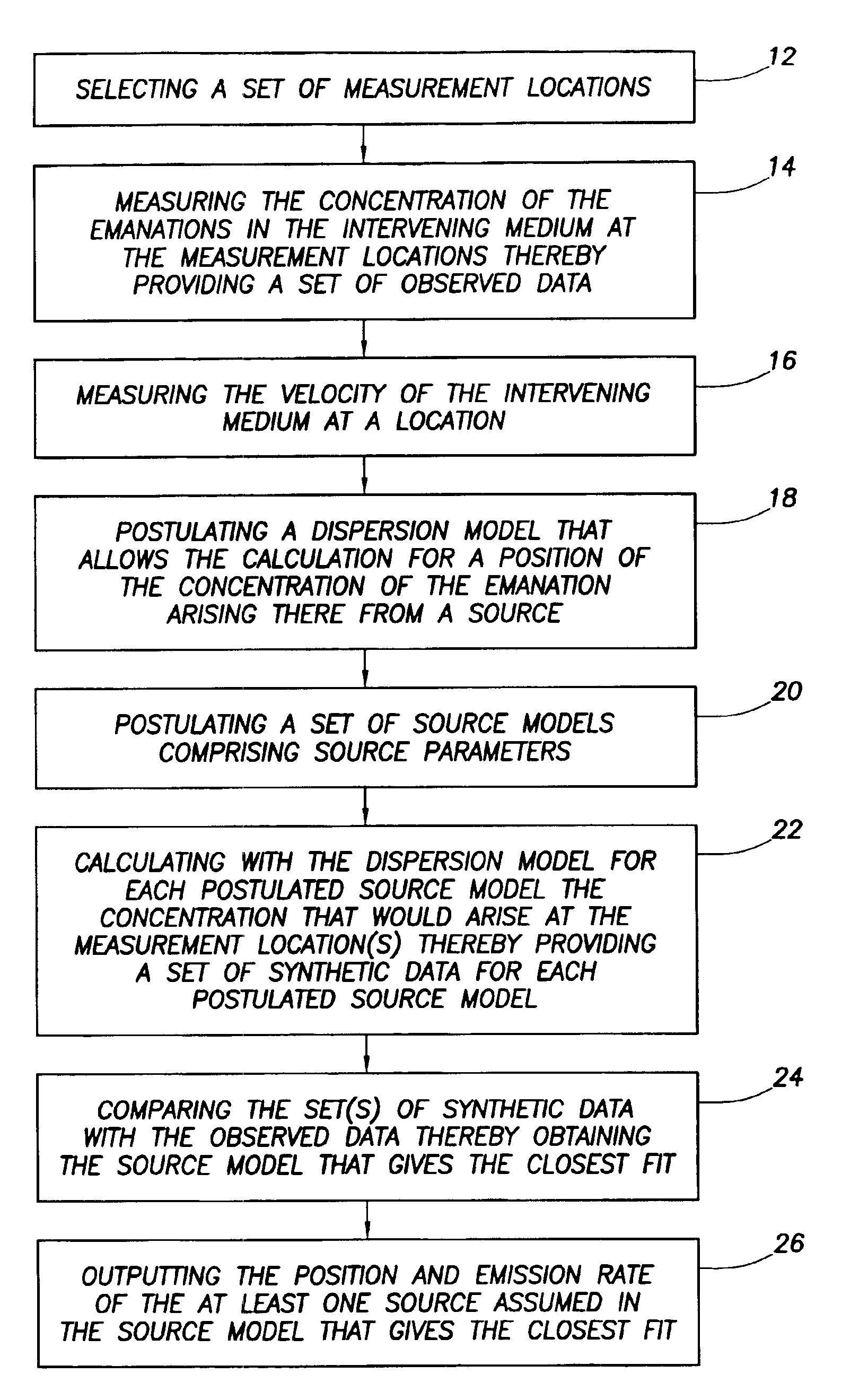
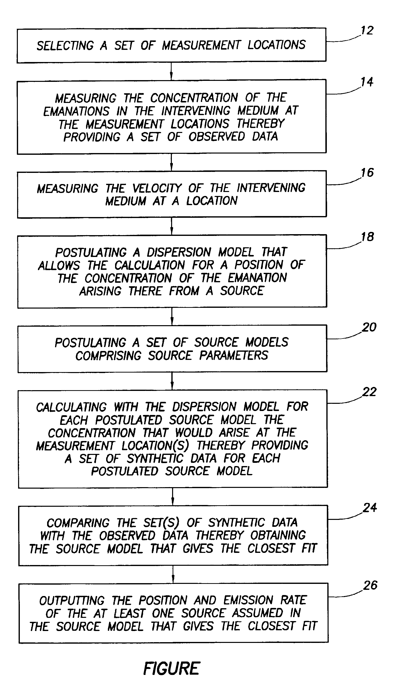
[0034]To overcome the above-mentioned disadvantage, provided is a method of determining the position and emission rate of at least one source of emanations into an intervening medium according to the present invention containing the steps of:[0035](a) selecting a set of measurement locations;[0036](b) measuring the concentration of the emanations in the intervening medium at the measurement locations to obtain a set of observed data;[0037](c) measuring the velocity of the intervening medium at a location;[0038](d) postulating a dispersion model that allows the calculation for a position of the concentration of the emanation arising there from a source;[0039](e) postulating a set of source models consisting of source parameters, such as the position(s) of assumed source(s) and assumed emission rate(s);[0040](f) calculating with the dispersion model for each postulated source model the concentration that would arise at the measurement location(s) to obtain a set of synthetic data for ...


PUM


Abstract

A method of determining the position and emission rate of at least one source of emanations into an intervening medium, which method comprises measuring the concentration of the emanations in the intervening medium at selected measurement locations to obtain observed data, and measuring the velocity of the intervening medium; postulating a dispersion model; postulating a source model containing source parameters, such as the position(s) of assumed source(s) and assumed emission rate(s); calculating with the dispersion model for a postulated source model the concentration that would arise at the measurement location(s) to obtain synthetic data for the postulated source model; comparing the synthetic data with the observed data to obtain the source model that gives the closest fit; and outputting the position and emission rate of the at least one source assumed in the source model that gives the closest fit.

Description

FIELD OF THE INVENTION[0001]The present invention relates to a method of determining the position and emission rate of at least one source of emanations into an intervening medium.BACKGROUND OF THE INVENTION[0002]The article Wilkinson et al, ‘Process site emission quantification and location from optical remote sensing measurements’ Proc. SPIE-Int. Soc. Opt. Eng; 1996, Vol. 2883, pages 355-364 discloses such a method.[0003]Such method contains the steps of:[0004](a) selecting a set of measurement locations;[0005](b) measuring the concentrations of the emanations in the intervening medium at the measurement locations to obtain a set of observed data;[0006](c) measuring the velocity of the intervening medium at a location;[0007](d) postulating a dispersion model that allows the calculation for a position of the concentration of the emanation arising there from a source;[0008](e) postulating a set of source models consisting of source parameters, such as the position(s) of assumed sour...

Claims


Application Information

Patent Timeline
IPC IPC(8): G01V9/00
CPCG01V9/007
Inventor ARCHIBALD, IAN GEORGEGILLESPIE, STEPHEN JOHNRICHARDSON, STEVEN ARTHURHIRST, WILLIAM JOSEPH SENIOR
Owner SHELL USA INC
Learn More