
Electro-kinetic air transporter and conditioner device with enhanced housing configuration and enhanced anti-microorganism capability

Inactive Publication Date: 2003-11-06
SHARPER IMAGE ACQUISITION LLC A DELAWARE LIMITED LIABILITY
View PDF99 Cites 63 Cited by
  • Summary
  • Abstract
  • Description
  • Claims
  • Application Information

AI Technical Summary

Benefits of technology

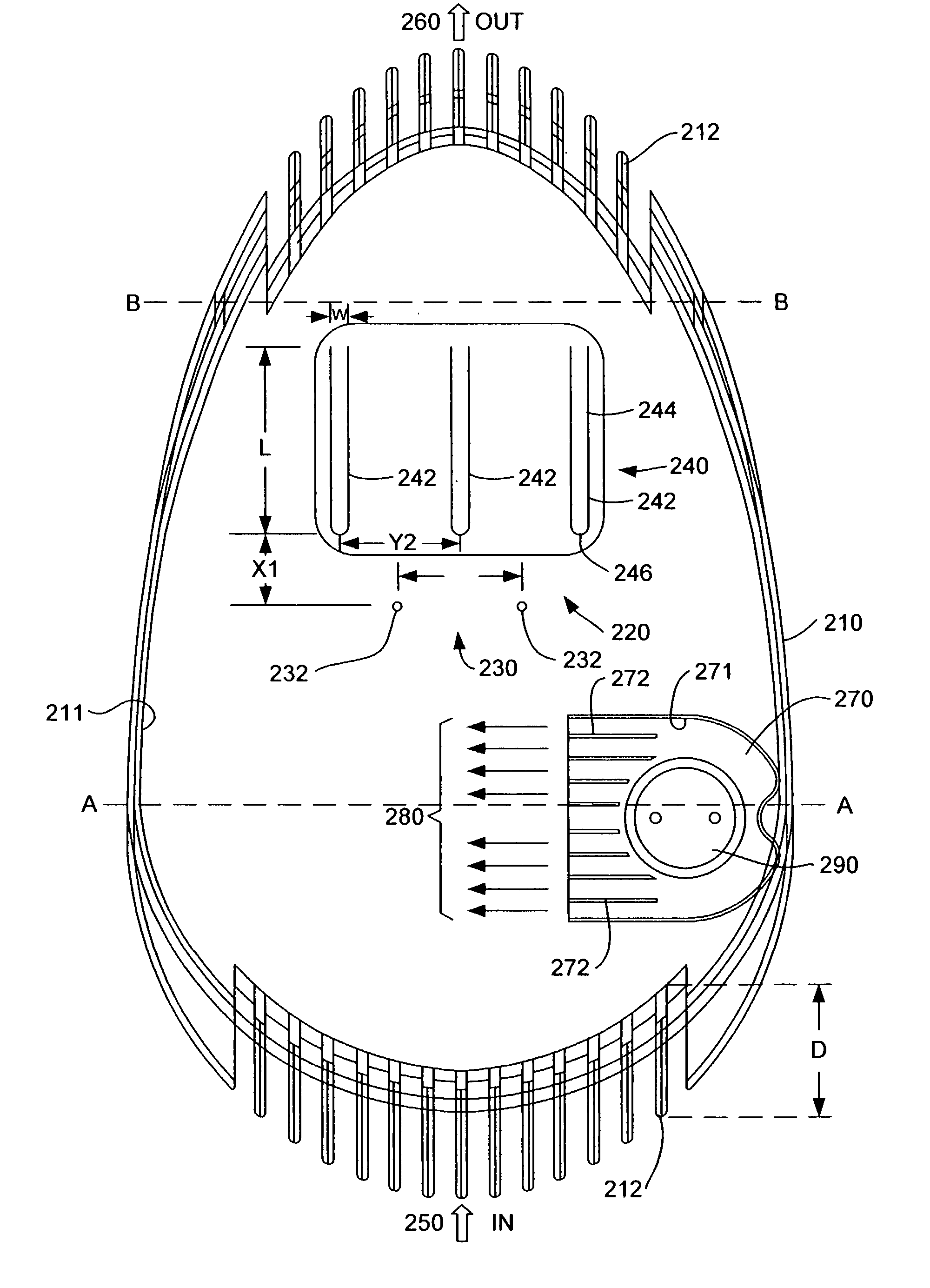
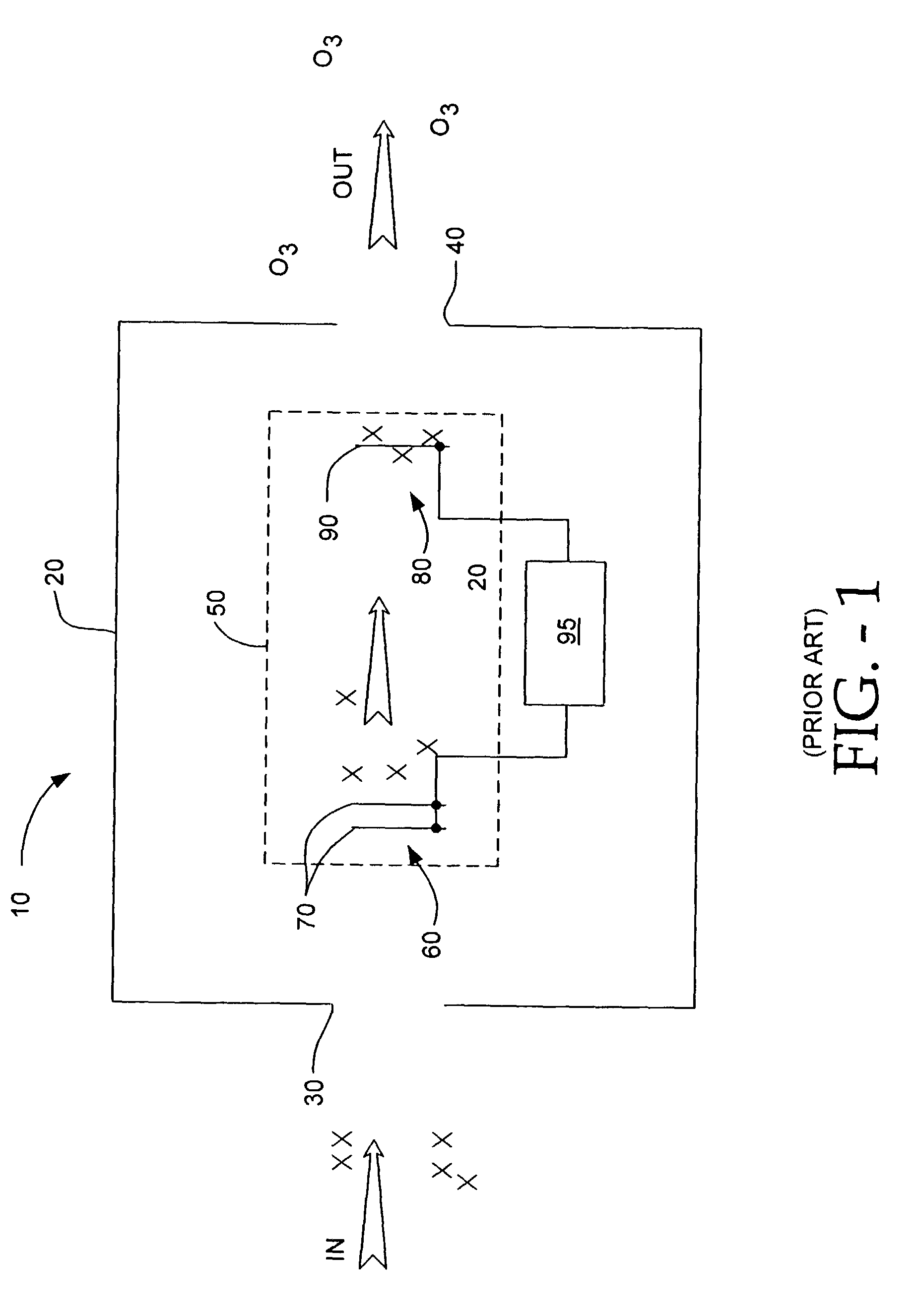
[0032] Embodiments of the present invention provide devices that fulfill the above described needs. It is an aspect of the present invention to reduce the amount of microorganisms within the airflow. An embodiment of the present invention has an ion generator to create an airflow and collect particulates, and a germicidal lamp to kill microorganisms. The housing is shaped to slow the airflow rate as the airflow passes the germicidal lamp, allowing a longer dwell time of the air in front of the germicidal lamp.
[0033] An aspect of the invention includes the germicidal lamp located upstream of the ion generator. An embodiment of the invention locates the germicidal lamp within the housing to maximize the amount of air irradiated, and to minimize the disturbance the lamp housing will cause to the airflow rate of the device. Another embodiment maximizes the amount of germicidal light that will directly shine on the airflow, without having to be reflected.
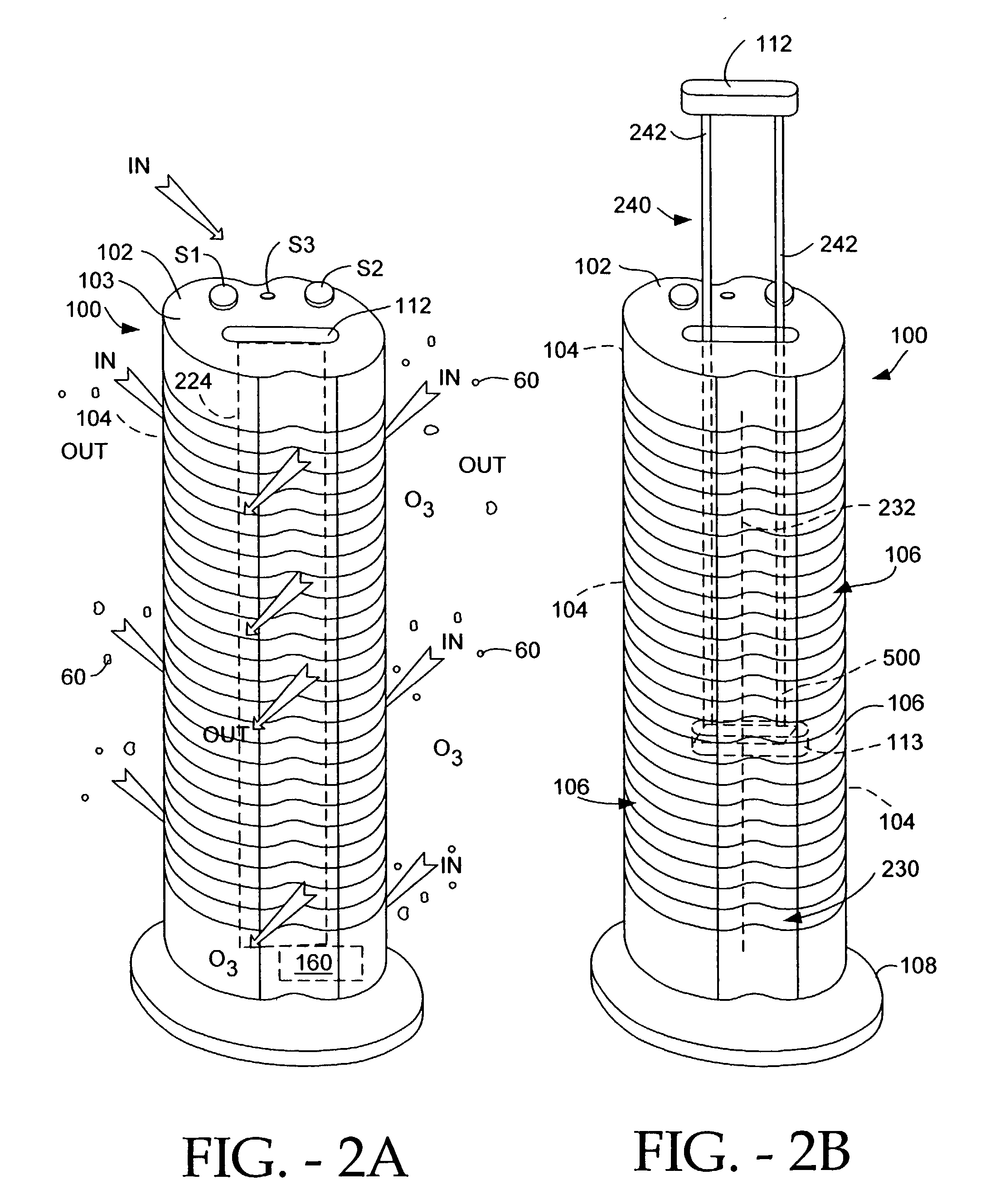
[0035] Another feature of an embodiment of the invention includes the ease of removeability of electrodes from the ion generator and ease of replacement of the germicidal lamp. An embodiment of the invention includes a rear panel that can be removed to expose the germicidal lamp for replacing. Another embodiment of the invention has second electrodes and a germicidal lamp that can be removed through the top of the housing for cleaning and / or replacement.
[0056] The upper surface 103 of the housing 102 includes a user-liftable handle member 112 to which is affixed a second array 240 of collector electrodes 242. The housing 102 also encloses a first array of emitter electrodes 230, or a single first emitter electrode shown here as a single wire or wire-shaped electrode 232. (The terms "wire" and "wire-shaped" shall be used interchangeably herein to mean an electrode either made from a wire or, if thicker or stiffer than a wire, having the appearance of a wire.) In the embodiment shown, handle member 112 lifts second array electrodes 240 upward causing the second electrode to telescope out of the top of the housing and, if desired, out of unit 100 for cleaning, while the first electrode array 230 remains within unit 100. As is evident from the figure, the second array of electrodes 240 can be lifted vertically out from the top 103 of unit 100 along the longitudinal axis or direction of the elongated housing 102. This arrangement with the second electrodes removable from the top 103 of the unit 100, makes it easy for the user to pull the second electrodes 242 out for cleaning. In FIG. 2B, the bottom ends of second electrodes 242 are connected to a member 113, to which is attached a mechanism 500, which includes a flexible member and a slot for capturing and cleaning the first electrode 232, whenever handle member 112 is moved upward or downward by a user. The first and second arrays of electrodes are coupled to the output terminals of ion generating unit 160.

Problems solved by technology

But ozone by itself may not be effective to kill microorganisms such as germs, bacteria, and viruses in the environment surrounding the device.
Often these devices are somewhat cumbersome, and have the size and bulk of a small filing cabinet.
Although such fan-powered devices can reduce or destroy microorganisms, the devices tend to be bulky, and are not necessarily silent in operation.

Method used


Image

  • Electro-kinetic air transporter and conditioner device with enhanced housing configuration and enhanced anti-microorganism capability
  • Electro-kinetic air transporter and conditioner device with enhanced housing configuration and enhanced anti-microorganism capability
  • Electro-kinetic air transporter and conditioner device with enhanced housing configuration and enhanced anti-microorganism capability

Examples


Embodiment Construction

of Air-Transporter-Conditioner System with Germicidal Lamp

[0060] FIGS. 3A-6 depict various embodiments of the device 200, with an improved ability to diminish or destroy microorganisms including bacteria, germs, and viruses. Specifically, FIGS. 3A-6 illustrate various preferred embodiments of the elongated and upstanding housing 210 with the operating controls located on the top surface 217 of the housing 210 for controlling the device 200.

[0061] FIGS. 3A-3E

[0062] FIG. 3A illustrates a first preferred embodiment of the housing 210 of device 200. The housing 210 is preferably made from a lightweight inexpensive material, ABS plastic for example. As a germicidal lamp (described hereinafter) is located within the housing 210, the material must be able to withstand prolonged exposure to class UV-C light. Non "hardened" material will degenerate over time if exposed to light such as UV-C. By way of example only, the housing 210 may be manufactured from CYCLOLAC.RTM. ABS Resin, (material d...


PUM


Abstract

An electro-kinetic air conditioner for removing particulates from the air creates an airflow using no moving parts. The airflow is subjected to UV radiation from a germicidal lamp within the device. The conditioner includes an ion generator that has an electrode assembly including a first array of emitter electrodes, a second array of collector electrodes, and a high voltage generator. The device can also include a third or leading or focus electrode located upstream of the first array of emitter electrodes, and / or a trailing electrode located downstream of the second array of collector electrodes, and / or an interstitial electrode located between collector electrodes, and / or an enhanced emitter electrode with an enhanced length in order to increase emissivity.

Description

CLAIM OF PRIORITY[0001] This application claims priority from provisional application entitled "ELECTRO-KINETIC AIR TRANSPORTER AND CONDITIONER DEVICE WITH ENHANCED HOUSING CONFIGURATION AND ENHANCED ANTI-MICROORGANISM CAPABLITY," application Ser. No. 60 / 340,702, filed Dec. 13, 2001 under 35 U.S.C. 119(e), which application is incorporated herein by reference. This application claims priority from provisional application entitled "FOCUS ELECTRODE, ELECTRO-KINETIC AIR TRANSPORTER-CONDITIONER DEVICES," application Ser. No. 60 / 306,479, filed Jul. 18, 2001 under 35 U.S.C. 119(e), which application is incorporated herein by reference. This application claims priority from and is a continuation-in-part of patent application "ELECTRO-KINETIC DEVICE WITH ENHANCED ANTI-MICROORGANISM CAPABILITY", application Ser. No. 09 / 774,198, filed Jan. 29, 2001, and incorporated herein by reference. This application claims priority from and is a continuation-in-part of U.S. patent application Ser. No. 09 / ...

Claims


Application Information

Patent Timeline
IPC IPC(8): A61L9/015A61L9/20A61L9/22B01D53/32B03C3/12B03C3/74B60H3/00C01B13/11H01T23/00
CPCA61L9/015H01T23/00A61L9/22B01D53/32B03C3/12B03C3/743B03C2201/14B60H3/0071C01B13/11C01B13/115C01B2201/12C01B2201/20C01B2201/22F24F2003/1667F24F2003/1682F24F2003/1685A61L9/20F24F8/22F24F8/30F24F8/40
Inventor TAYLOR, CHARLES E.LAU, SHEK FAIPARKER, ANDREW J.CHRISTIANSON, TRISTAN M.SNYDER, GREGORY S.MCKINNEY, EDWARD C. JR.
Owner SHARPER IMAGE ACQUISITION LLC A DELAWARE LIMITED LIABILITY
Learn More