Cap mounted light

Inactive Publication Date: 2005-05-24
SCHLAPKOHL THOMAS P
View PDF21 Cites 21 Cited by
  • Summary
  • Abstract
  • Description
  • Claims
  • Application Information

AI Technical Summary

Benefits of technology

[0008]In an advantage provided by this invention, a hat illumina

Problems solved by technology

A drawback associated with such prior art devices is the difficulty locating and actuating what are typically micro switches.
An additional drawback is the bulk, weight and aesthetically displeasing appearance of light assemblies attac

Method used


Image

  • Cap mounted light
  • Cap mounted light
  • Cap mounted light

Examples


Embodiment Construction

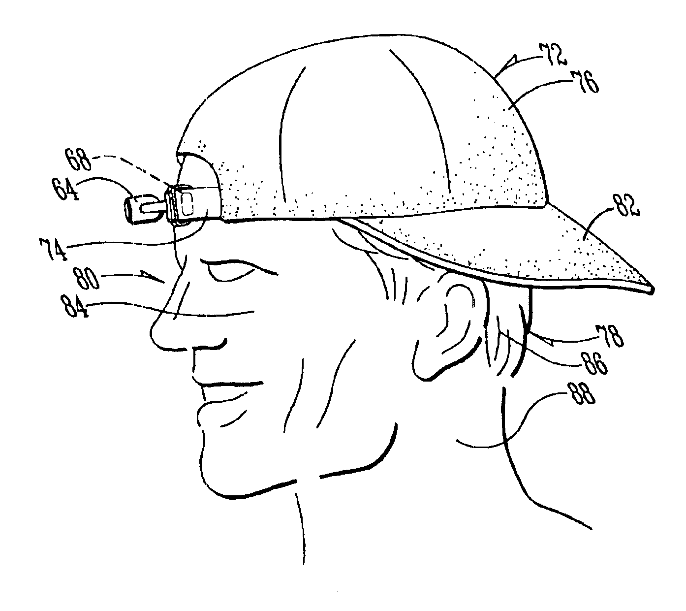
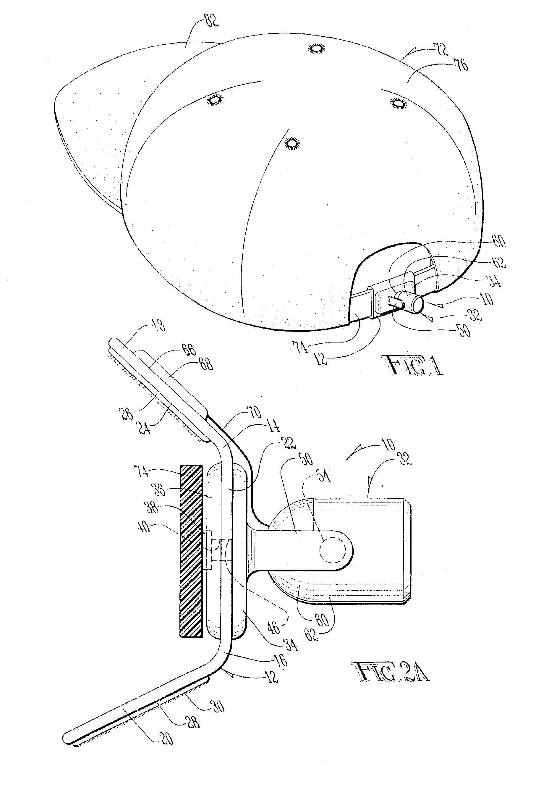
[0029]A cap illumination system according to this invention is shown generally as (10) in FIG. 1. The cap illumination system (10) includes a retaining belt (12) constructed of woven nylon or similar flexible material. (FIG. 2A). Although the retaining belt (12) may be of any suitable dimensions, in the preferred embodiment, the retaining belt (12) is preferably between two and fifty centimeters square and between 0.5 and 5 mm. thick. The retaining belt (12) is even more preferably eight centimeters square and two millimeters thick.

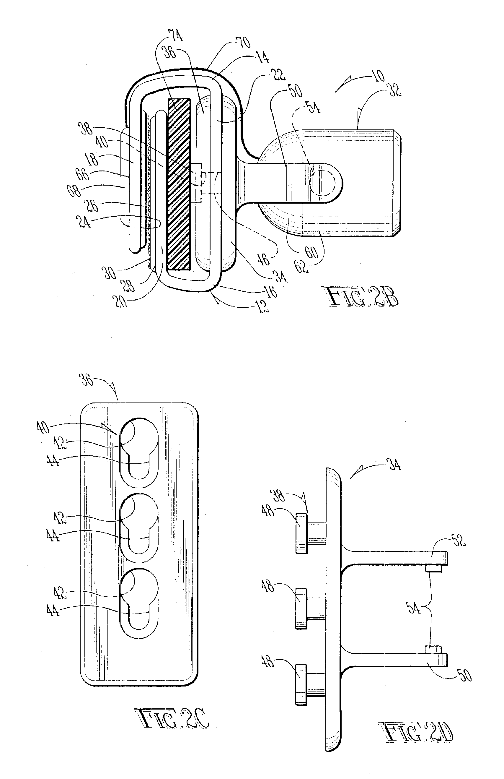
[0030]As shown in FIG. 2A the retaining belt (12) is preferably provided with a first crease (14) and second crease (16), dividing the retaining belt (12) into a first flap (18), a second flap (20) and a body (22). Secured to an interior face (24) of the first flap (18) by adhesive, sewing, or similar securement means, is a first piece (26) of hook and latch material. Secured to an exterior face (28) of the second flap (20) is a second piece (30) of hook ...


PUM


Abstract

An illumination system for a hat is provided. The system includes a light pivotally connected to an attachment mechanism constructed of hook and latch material. The hook and latch material is provided around an adjustment band of a typical “baseball cap.” Batteries and a touch sensitive switch are coupled to the light with the touch sensitive switch facing inward. The cap is usable in its standard orientation during the day to shield the suns rays from the user's eyes. At night, or indoors, the cap may be reversed. Whereas in the standard orientation the touch sensitive switch is blocked from contact with the skin by the user's hair, in the reversed orientation the touch sensitive switch contacts the user's forehead, thereby actuating the light automatically for use.

Description

[0001]This application is a divisional of Ser. No. 10 / 173,499 filed on Jun. 17, 2002 now U.S. Pat. No. 6,634,031.BACKGROUND OF THE INVENTION[0002]1. Field of the Invention[0003]The present invention relates in general to an illumination system for a hat and, more specifically, an illumination system for a bat with an automatic touch sensitive activation switch which automatically actuates a light upon reversal of the hat.[0004]2. Description of the Prior Art[0005]Illuminated hats are well known in the art. Typically, such devices include forward directed lights such as those described in U.S. Pat. No. 5,741,060, or devices used to illuminate the hat itself, such as that described in U.S. Pat. No. 6,168,286. The devices are typically actuated by a mechanical switch or the like.[0006]A drawback associated with such prior art devices is the difficulty locating and actuating what are typically micro switches. An additional drawback is the bulk, weight and aesthetically displeasing appea...

Claims


Application Information

Patent Timeline
IPC IPC(8): A42B1/00A42B1/24F21V23/04F21V21/08F21L14/00F21V21/088F21V21/14
CPCA42B1/242F21L14/00F21V21/0832F21V21/0885F21V23/0414A42B1/244F21V21/145Y10S362/802F21Y2101/02F21Y2115/10
Inventor SCHLAPKOHL, THOMAS P.
Owner SCHLAPKOHL THOMAS P
Why Eureka
Try Eureka