Vehicle securing mechanism for a dynamometer

a technology of dynamometer and securing mechanism, which is applied in the direction of vehicle tractive/propulsive power measurement, force/torque/work measurement apparatus, instruments, etc., can solve the problems of slow method of securement, inefficiency, and less available time for productive use of dynamometer, so as to increase safety

Inactive Publication Date: 2006-03-02
DRAG TAG PTY LTD
View PDF11 Cites 16 Cited by
  • Summary
  • Abstract
  • Description
  • Claims
  • Application Information

AI Technical Summary

Benefits of technology

[0010] The vehicle engaging component of the securing mechanism should engage a structural part of the vehicle that is directly associated with the drive wheel. For example, for a vehicle having driven rigid axle rear wheels, this structural part may be the rear axle housing, or if the driven wheels are independently suspended it may be at a location directly associated with the knuckle assembly of the wheel hub, for example a bracket thereon which mounts a suspension component such as a spring or shock absorber. The reason for the vehicle engaging component to engage a structural part that is directly associated with the drive wheel is

Problems solved by technology

However this method of securement is slow and thereby inefficient becau

Method used


Image

  • Vehicle securing mechanism for a dynamometer
  • Vehicle securing mechanism for a dynamometer
  • Vehicle securing mechanism for a dynamometer

Examples


Embodiment Construction

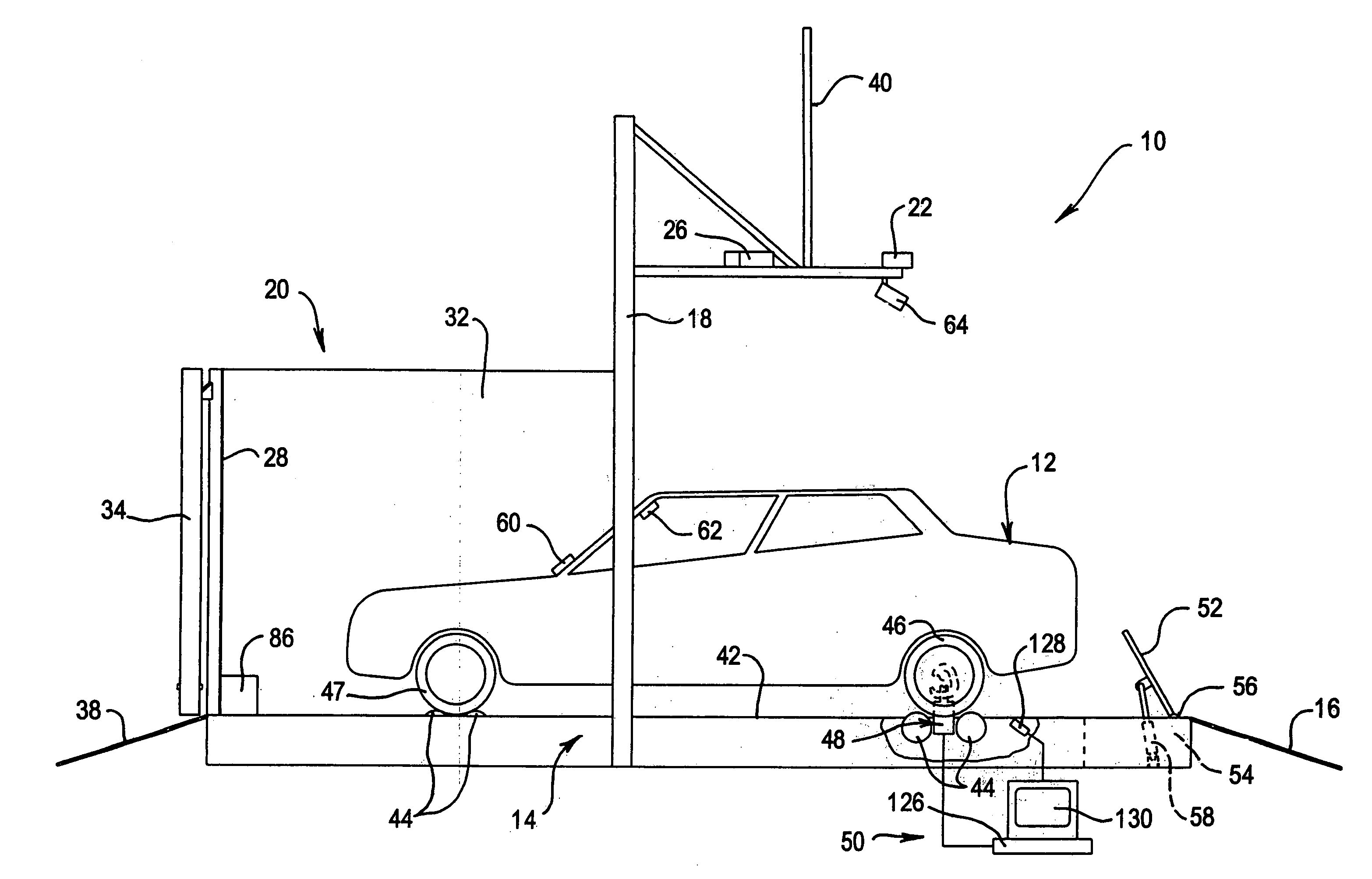
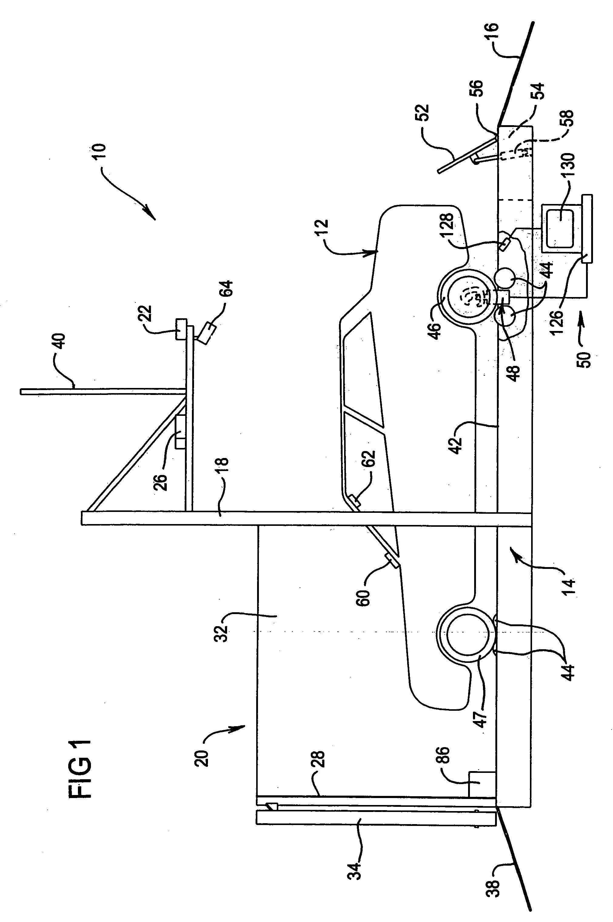
[0024]FIG. 1 shows apparatus 10 for simulated driving of a motor car 12 whilst the car 12 remains stationary as comprising a chassis dynamometer 14 onto which the car 12 may be driven via an entry ramp 16 of the dynamometer 14. The chassis dynamometer 14 has a frame 18 associated therewith which carries other components of the apparatus 10. These other components include some portions of a viewing screen arrangement 20 and projectors 22, 24, 26 of a visual display system. The viewing screen arrangement 20 includes a front screen portion 28 that extends across the front of the motor car 12 and side screen portions 30, 32 that extend, respectively, a distance along each side of the motor car 12 (the side screen portion 30 has been omitted from FIG. 1 for clarity). Each side screen portion 30 and 32 is angled at 120° from the front screen portion 28. There are three projectors 22, 24, 26 of the visual display system mounted on the frame 18, each for projecting virtual scenic imagery on...


PUM


Abstract

A securing mechanism for attachment to a chassis dynamometer for securing a motor vehicle on the chassis dynamometer, the securing mechanism including a vehicle engaging component which, when the securing mechanism is attached to the chassis dynamometer, is engageable with a vehicle on the dynamometer to thereby secure the vehicle to ensure it remains substantially stationary on the dynamometer, at least one actuator and a load beam for moving the vehicle engaging component in three orthogonal directions and into engagement with the vehicle for securing the vehicle wherein the actuator is for use with a remotely operable control system. The vehicle engaging component may be a pin for engaging hook shaped bracket that is fixed to the vehicle's axle housing of the vehicle.

Description

TECHNICAL FIELD [0001] The present invention relates to a securing mechanism for attachment to a chassis dynamometer for securing a motor vehicle on the dynamometer. The invention also relates to apparatus that includes a chassis dynamometer for testing or simulated driving of a motor vehicle that includes the securing mechanism. The invention furthermore relates to a bracket for attachment to a vehicle for use with the securing mechanism. BACKGROUND [0002] Chassis dynamometers are used to measure various performance parameters of motor vehicles from which diagnoses can be made of possible engine, drive train or suspension faults in the vehicle. A chassis dynamometer may also be a component in apparatus for simulated driving of a motor vehicle, for example for driver training or simulated racing as disclosed in the applicant's co-pending International application No. PCT / AU2005 / ______ entitled “Apparatus for Simulated Driving of a Motor Vehicle” filed concurrently with the present a...

Claims


Application Information

Patent Timeline
IPC IPC(8): G01L3/26G01M17/007G09B9/042
CPCG09B9/042G01M17/0076
Inventor BOND, NEVILLE J.
Owner DRAG TAG PTY LTD
Why Eureka
Try Eureka