Quick set clamp device

a clamp device and quick-set technology, applied in the direction of clamps, manufacturing tools, and surfaces, can solve the problems of obstructing the placement of objects, user use, and time required, and achieve the effects of increasing the grasping force of the first and second engagement members, increasing the grasping of the binding member on the slide shaft, and increasing the grasping for

Active Publication Date: 2007-11-15
ALBERTI JOHN L
View PDF5 Cites 13 Cited by
  • Summary
  • Abstract
  • Description
  • Claims
  • Application Information

AI Technical Summary

Benefits of technology

[0011] Yet another objective of the present invention is to provide a quick clamp device that operates by sliding rather than rotating members when securing or removing the device from an object or workpiece. A feature of the device is a slide shaft that is urged, via a person's thumb, from a retracted to a binding position relative to a clamp frame. An advantage of the device is that the person can hold the clamp frame between the palm and fingers while pushing upon a knob portion of the slide shaft with their thumb to force a first engagement member, on the opposing end of the slide shaft, into forcible engagement with the object or workpiece until the object or workpiece forcibly engages a second engagement member secured to an opposing portion of the clamp frame.
[0012] Still another objective of the present invention is to provide a quick clamp device that substantially maintains the position of the slide shaft relative to the frame after the first and second engagement members engage the object or workpiece. A feature of the device is a binding member having a first portion that slidably engages the slide shaft, and having a second portion that engages a retaining member. Another feature is a biasing member that cooperates with the binding member and retaining member to skew or angle the position of the binding member relative to the slide shaft. An advantage of the device is that the binding member promotes unrestricted movement of the slide shaft through an aperture in the binding member in a direction toward an object until the object or workpiece is secured between the first and second engagement members. Another advantage of the device is the binding member prevents retracting the slide shaft through the aperture until a person manually urges the binding member to a position that releases the slide shaft thereby allowing the object or workpiece to be separated from the clamp device.
[0013] Another objective of the present invention is to provide a quick clamp device that allows the force imparted by the engagement members upon the object or workpiece to be increased after initially securing the clamp device to the object or workpiece via the slide shaft. A feature of the device is a retaining member that rotationally inserts into a threaded aperture in an outer first end portion of the clamp frame while the retaining member engages the binding member. An advantage of the device is that by inserting the retaining member into the clamp frame, the grasp of the binding member upon the slide shaft increases, while at the same time increasing the force applied from the slide shaft to the first engagement member, thereby increasing the grasp of the first and second engagement members upon the object or workpiece.
[0014] Another objective of the present invention is to provide pads that engage and secure an object or workpiece to the clamp device. A feature of the device is a swivel and “O” ring combination that cooperate with a pad to retain a selected pad position after the pad is moved by a user of the clamp device or by the urging of the object or workpiece. An advantage of the device is that after removing an object or workpiece, a replacement object or workpiece having substantially the same configuration and dimensions as the removed object or workpiece is quickly positioned to engage top walls of the pads thereby reducing the time required to secure the replacement object or workpiece to the clamp device.
[0015] Briefly, the invention provides a clamp device comprising a clamp frame configured and dimensioned to removably receive an object; a slide shaft having a longitudinal dimension that cooperates with said clamp frame to removably secure together portions of the object, said slide shaft being disposed such that a user is capable of urging said slide shaft toward said clamp frame via a thumb portion of the user's hand while at least one finger of the same hand supports said clamp frame; a biasing member disposed upon said slide shaft, said biasing member having a first end that engages an outer first end portion of said clamp frame; a binding member having a first portion that slidably engages said slide shaft; a retaining member retractably secured to said outer first end portion of said clamp frame, said retaining member engaging a second portion of said binding member; and a first engagement member secured to a first end of said slide shaft, and a second engagement member secured to an inner second end portion of said clamp frame, whereby said slide shaft and said first engagement member secured thereto are urged toward said second engagement member until securing an object between said first and second engagement members, whereupon, said retaining member is inserted into said clamp frame thereby urging said retaining member, binding member and biasing member to cooperate to move the position of said slide shaft relative to said clamp frame to facilitate forceful engagement between said first engagement member and a first portion of the object, and to facilitate forceful engagement between said second engagement member and a second portion of the object.
[0016] The invention further provides a clamp comprising a substantially C configured clamp frame; a slide shaft having a longitudinal dimension that cooperates with said clamp frame to removably secure together portions of the object, said slide shaft being disposed such that a user is able to urge said slide shaft toward said clamp frame while the user supports said clamp frame; a biasing member adjacently disposed to said slide shaft, said biasing member having a first end that engages an outer first end portion of said clamp frame; a binding member having a first portion that slidably engages said slide shaft; a retaining member disposed to engage a second portion of said binding member; and a first engagement member secured to a first end of said slide shaft, and a second engagement member secured to an inner second end portion of said clamp frame, whereby said slide shaft and said first engagement member secured thereto are urged toward said second engagement member until securing an object between said first and second engagement members, whereupon, said retaining member, binding member and biasing member cooperate to move the position of said slide shaft relative to said clamp frame to facilitate forceful engagement between said first engagement member and a first portion of the object, and to facilitate forceful engagement between said second engagement member and a second portion of the object.

Problems solved by technology

One problem with prior art C clamps is the time required to rotate the handle to position the engagement members of the clamp within depressions or cavities of object, then retract the engagement members sufficiently to avoid protuberances corresponding to the depressions or cavities.
Another problem with prior art C clamps is that the user has to use two hands to operate the C clamp; one hand to rotate the handle while the other hand holds a frame portion of the C clamp.
Another problem with prior art slide clamps is that the table or base limits space between the engagement members thereby obstructing placement of the object such that depressions and cavities in the object are not accessible by the engagement members.

Method used


Image

  • Quick set clamp device
  • Quick set clamp device
  • Quick set clamp device

Examples


Embodiment Construction

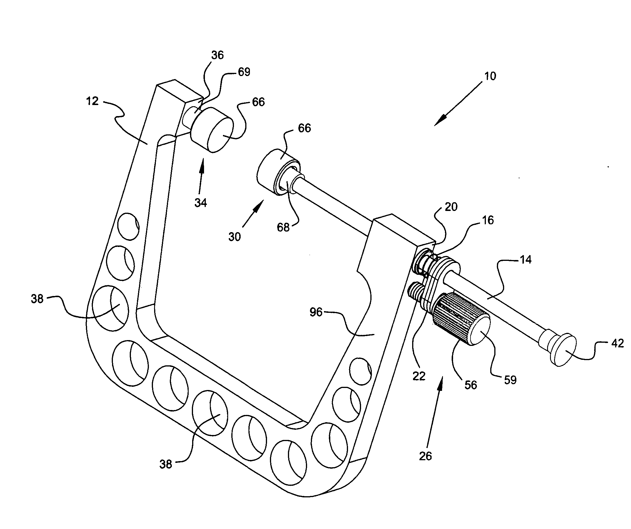
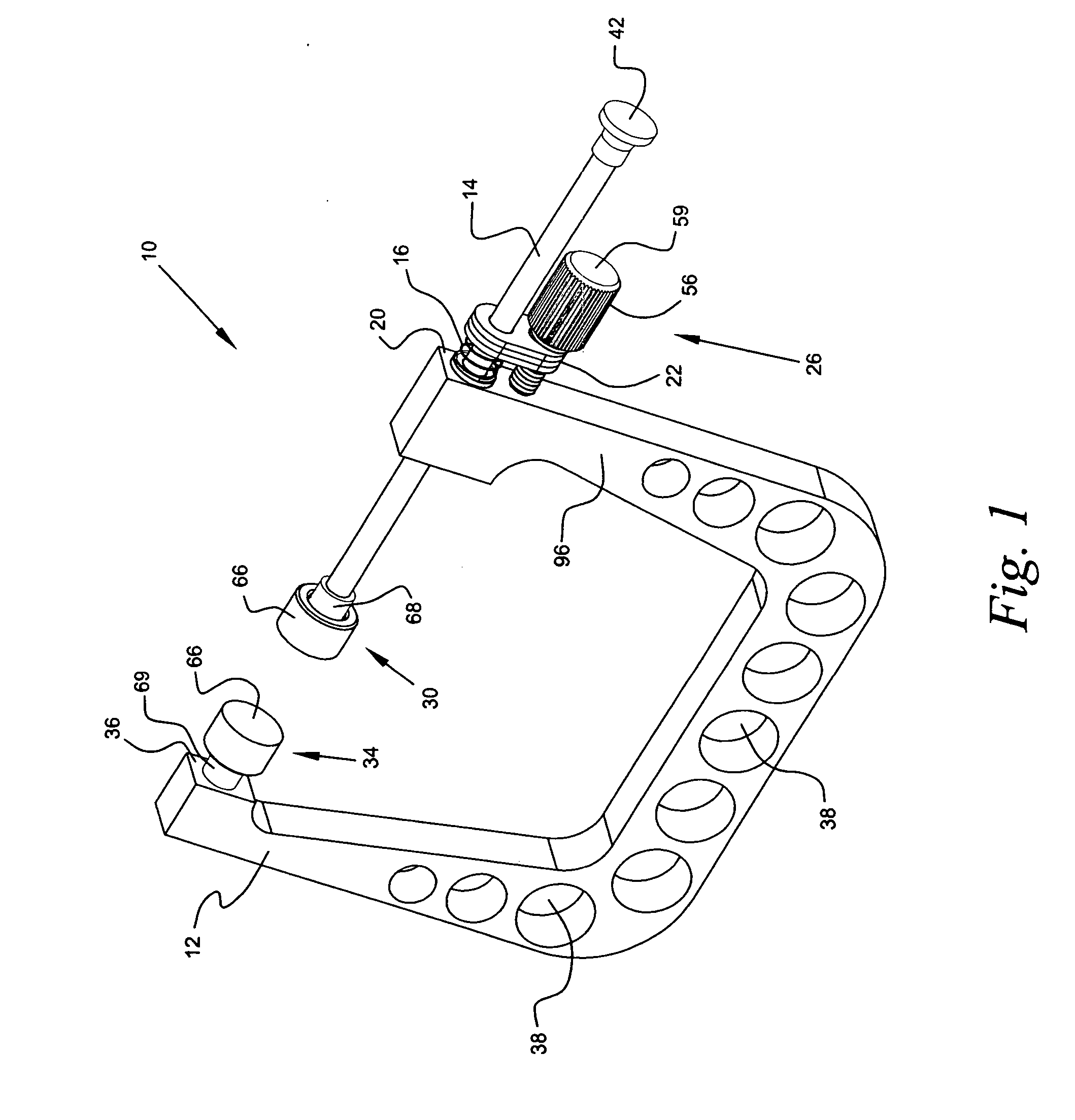
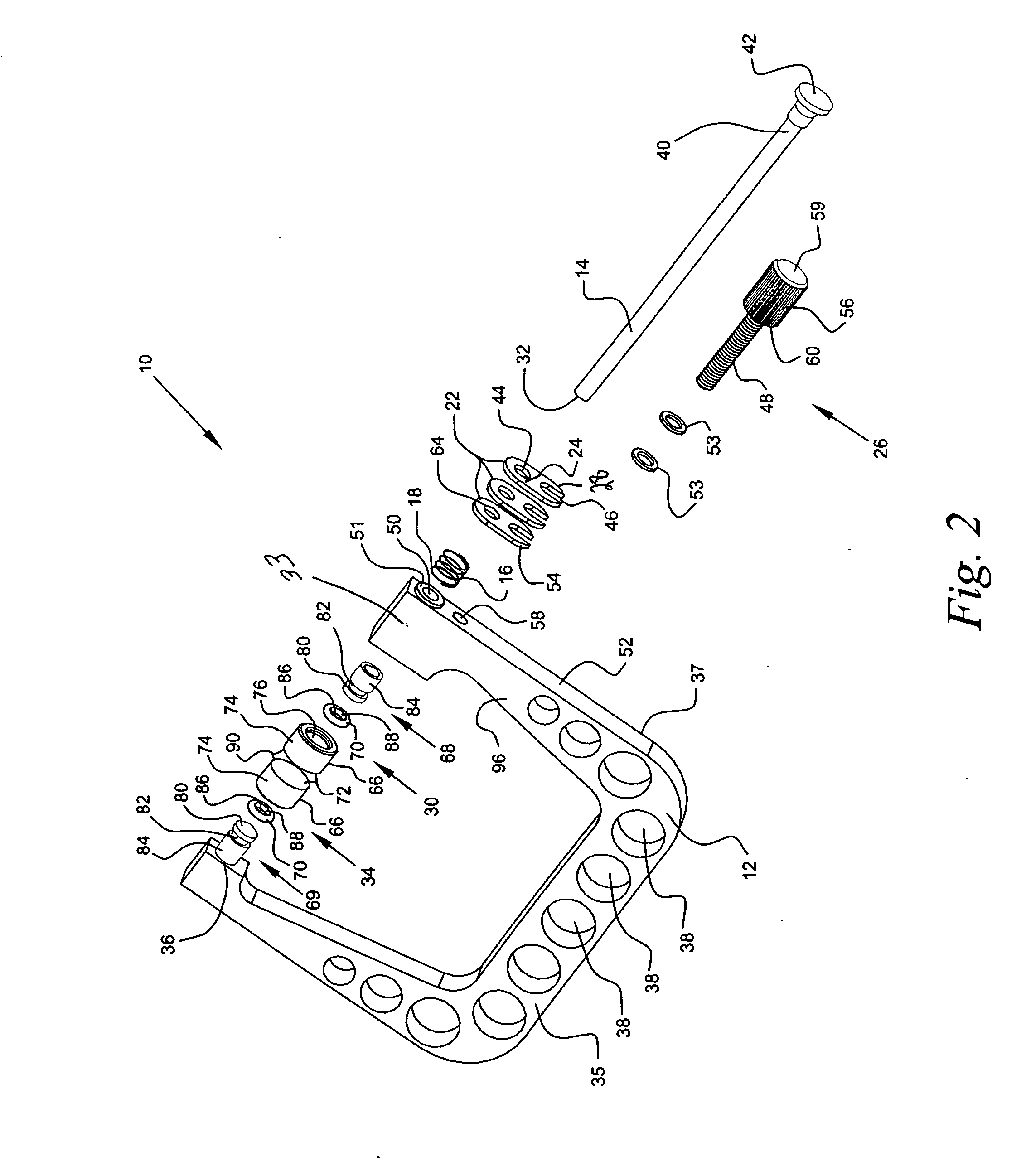
[0029] Referring now to the drawings, a quick set clamp device operable by one hand of a user in accordance with the present invention is denoted as numeral 10. The clamp device 10 includes a clamp frame 12 configured and dimensioned to removably receive a myriad of objects including but not limited to wood products, metal items and portions of musical instruments; a slide shaft 14 having a longitudinal dimension that cooperates with the clamp frame 12 to removably secure the clamp device 10 to an object; a biasing member 16 adjacently disposed to the slide shaft 14, the biasing member 16 having a first end 18 that engages an outer first end portion 20 of the clamp frame 12; a binding member 22 having a first portion 24 that slidably engages the slide shaft 14; a retaining member 26 removably secured to the outer first end portion 20 of the clamp frame 12, the retaining member 26 engaging a second portion 28 of the binding member 22; a first engagement member 30 secured to a first e...


PUM


Abstract

A quick set clamp device 10 includes a clamp frame 12, a slide shaft 14 having a longitudinal dimension that cooperates with the clamp frame 12 to removably secure the clamp frame device 10 to an object, a biasing member 16 adjacently disposed to the slide shaft 14, the biasing member 16 having a first end 18 that engages an outer first end portion 20 of the clamp frame 12, a binding member 22 having a first portion that slidably engages the slide shaft 14, a retaining member 26 retractably secured to the outer first end portion 20 of the clamp frame 12, the retaining member 26 engaging a second portion 28 of the binding member 22, a first engagement member 30 secured to a first end 32 of the slide shaft 14, and a second engagement member 34 secured to an inner second end portion 36 of the clamp frame 12.

Description

BACKGROUND OF THE INVENTION [0001] 1. Field of the Invention [0002] The present invention relates to a quick set clamp device, and more particularly, to a substantially “C” configured quick set clamp device operable by one hand of a user while the user's other hand holds an object or workpiece. [0003] 2. Background of the Prior Art [0004] A myriad of clamp sizes and configurations are obtainable for securing together different objects or portions of a workpiece. The more common clamps include C-configured clamps—“C clamps” that are secured to an object via a rotating handle, and slide clamps that include a clamp mechanism and a base or table having a sliding object engagement member that slides toward a stationary object engagement member to ultimately secure an object therebetween. [0005] The C clamps provide sufficient space between opposite engagement members to allow an object to be unobstructedly disposed between the engagement members, thereby providing engagement member acces...

Claims


Application Information

Patent Timeline
Patent Type & Authority Applications(United States)
IPC IPC(8): B25B1/10
CPCB25B5/163B25B5/067
Inventor ALBERTI, JOHN L.
Owner ALBERTI JOHN L
Why Eureka
Try Eureka