Sway brace clamp and connector assembly

a technology of connectors and clamps, which is applied in the direction of scaffold accessories, curtain suspension devices, furniture parts, etc., can solve the problems of increasing the time and labor involved in installation, the cost of installation, so as to ensure the stability of the clamp and the rod, the effect of reliably supporting heavy loads and being easy to install

Inactive Publication Date: 2005-05-24
NIBCO INC
View PDF40 Cites 34 Cited by
  • Summary
  • Abstract
  • Description
  • Claims
  • Application Information

AI Technical Summary

Benefits of technology

[0009]It is one advantage of the invention to provide an interlocking swivel connector for attachment to an existing system supporting a suspended load below a ceiling, beam or floor without the need to disassemble or disconnect any components of the system. The connector is easy to install and inexpensive to manufacture. The connector is removably or permanently attachable to a sway brace clamp or attachment to form a connector-clamp assembly. The assembly is capable of reliably supporting heavy loads against adverse sway and seismic disturbances.
[0010]It is another advantage of the invention to provide a sway cable brace clamp or fitting for securely attaching to a bracing cable and for supporting a suspended load below a ceiling, beam or floor. The cable clamp is easy to install and inexpensive to manufacture. The cable clamp is capable of reliably supporting heavy loads against adverse sway and seismic disturbances.
[0011]In accordance with one embodiment, a connector is provided for retrofit attachment to a threaded rod extending from a support structure for supporting a suspended load against sway and seismic disturbances. The connector generally comprises a longitudinal axis and a pivot pin defining a rotation axis generally perpendicular to the longitudinal axis, a first arm pivotable about the rotation axis and a second arm pivotable about the rotation axis. The first arm generally comprises a proximal section, a medial section and a distal section. The first arm proximal section is pivotably attached to the pivot pin. The first arm medial section is angled relative to the proximal section of the first arm and has a slot extending generally upwards from a lower edge thereof. The first arm distal section is angled relative to the medial section of the first arm and has a slot extending generally upwards from a lower edge thereof. The first arm distal section and the medial section of the first arm are connected at a junction to form a curved wall between the slots of the first arm. The second arm generally comprises a proximal section, a medial section and a distal section. The second arm proximal section is pivotably attached to the pivot pin. The second arm medial section is angled relative to the proximal section of the second arm and has a slot extending generally downwards from an upper edge thereof. The second arm distal section is angled relative to the medial section of the second arm and has a slot extending generally downwards from an upper edge thereof The second arm distal section and the medial section of the second arm are connected at a junction to form a curved wall between the slots of the second arm. Advantageously, the arms are pivotable to interlock and mate with one another such that the slot of the medial section of the first arm is aligned with the slot of the medial section of the second arm and the slot of the distal section of the first arm is aligned with the slot of the distal section of the second arm to form a passage bounded by the curved walls and flanked by the slots for capturing the rod therebetween.
[0012]In accordance with another embodiment, a seismic connector is provided for retrofit attachment to a support element of an installation. The connector generally comprises a pivotable first arm and a pivotable second arm. The first arm generally comprises a first curved section flanked by a first slot and a second slot of the first arm. The second arm generally comprises a second curved section flanked by a first slot and a second slot of the second arm. Advantageously, interlocking of the slots of the first arm with the second arm to receive selected portions of the second arm within the slots of the first arm and interlocking of the slots of the second arm with the first arm to receive selected portions of the first arm within the slots of the second arm forms an opening generally circumscribed by the first and second curved sections for receiving the support element without requiring disassembly of the installation.
[0013]In accordance with yet another embodiment, a connector is provided for retrofit attachment to a support. The connector generally comprises a first arm and a second arm. The first arm has a proximal end and a distal end and a first curved wall therebetween. The first arm includes a first slot having a base face and positioned between the first curved wall and the proximal end of the first arm. The second arm has a proximal end and a distal end and a second curved wall therebetween. The second arm includes a first slot having a base face and positioned between the second curved wall and the proximal end of the second arm. Advantageously, the arms are interlockable such that the base faces of the slots abut against one another to form a passage generally bounded by the curved walls for receiving the support.
[0014]In accordance with one embodiment, a sway brace assembly is provided. The assembly generally comprises a connector for retrofit attachment to a rod extending from a support surface and an attachment device coupled to the connector for attaching the connector to a brace. The connector generally comprises a first arm and a second arm. The first arm has a proximal end, a distal end, a first angled section therebetween and a first slot positioned between the first angled section and the proximal end of the first arm. The second arm has a proximal end, a distal end, a second angled section therebetween and a first slot positioned between the second angled section and the proximal end of the second arm. Advantageously, at least one of the arms is pivotable about a rotation axis of the connector so that when the arms mate at least a portion of each of the arms is received in a corresponding one of the slots, the slots are aligned with one another and the angled sections form a passage for receiving the rod therebetween.

Problems solved by technology

Disadvantageously, this adds to the time and labor involved in the installation, and hence to the cost of the installation.
Moreover, and undesirably, many conventional connectors used to attach the clamp to the rod can be expensive, difficult to install and not capable of reliably sustaining heavy loads.
Disadvantageously, the cable brace attachments commonly used in the industry are difficult to install and expensive.
Additionally, and undesirably, conventional cable brace attachments may not be suited for reliably sustaining heavy loads.

Method used


Image

  • Sway brace clamp and connector assembly
  • Sway brace clamp and connector assembly
  • Sway brace clamp and connector assembly

Examples


Embodiment Construction

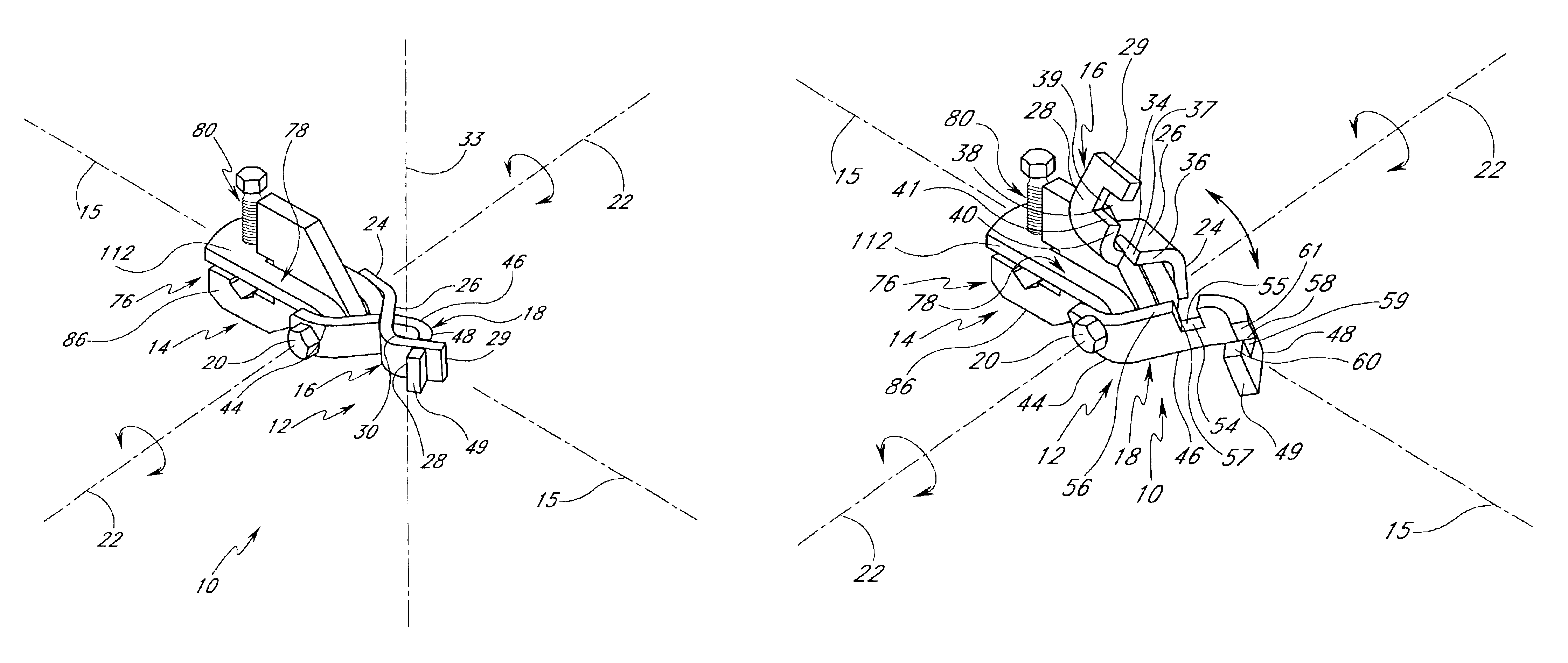
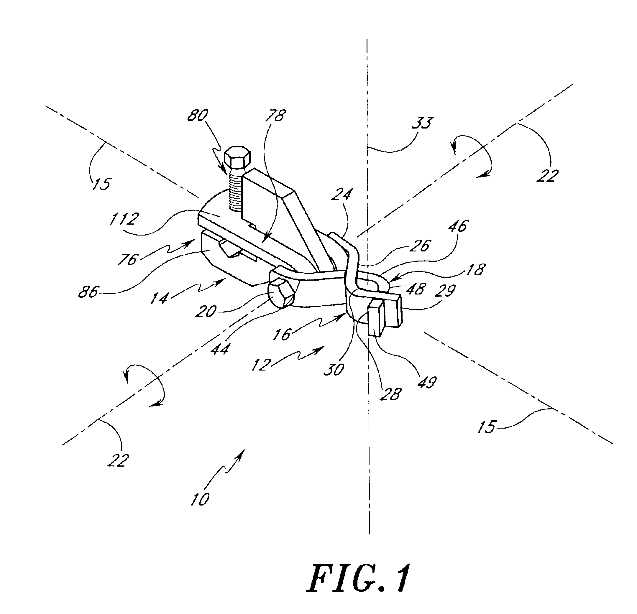
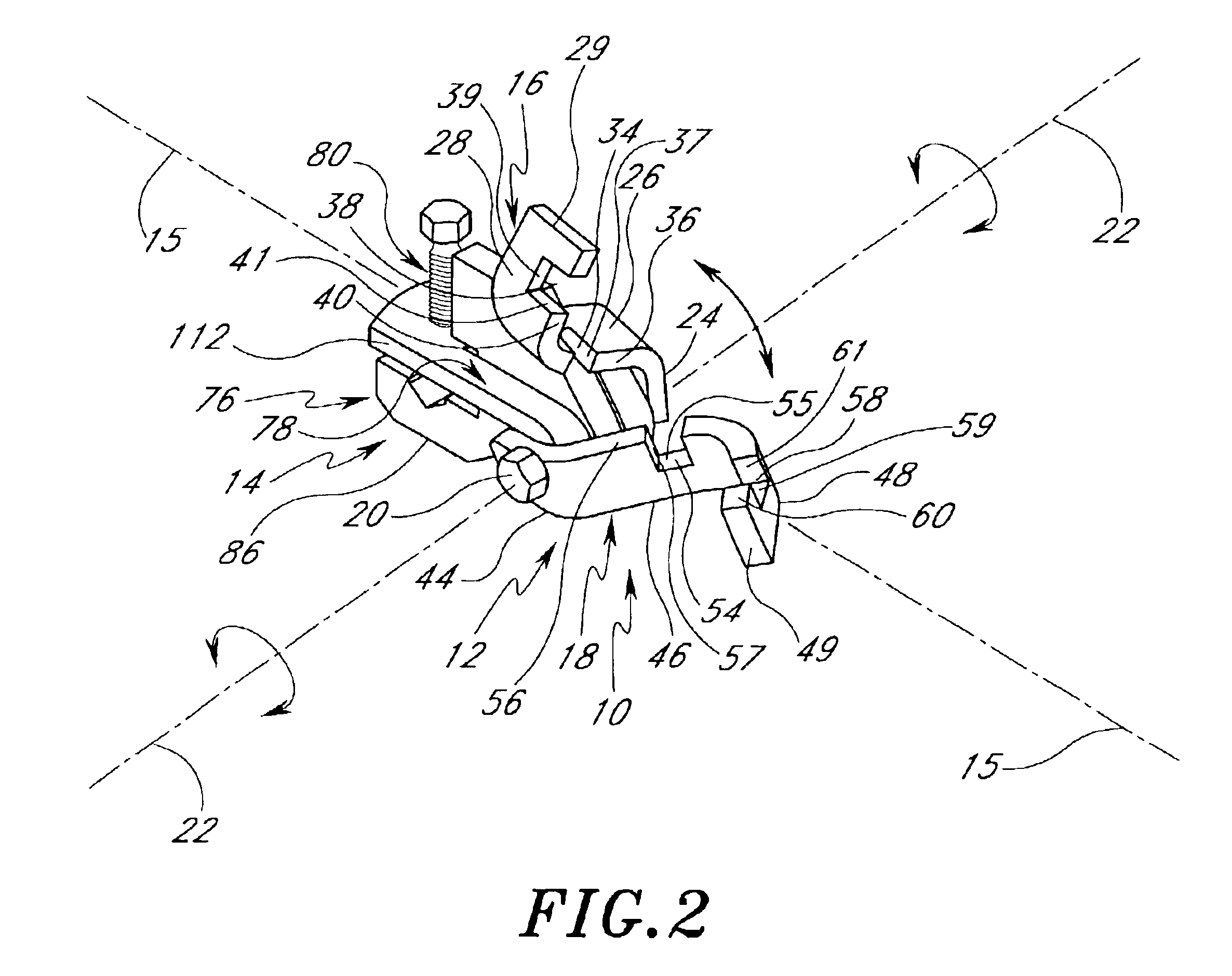
[0063]The preferred embodiments of the invention described herein relate generally to devices for bracing pipes and other loads suspended from or below ceilings, floors, beams, walls and the like, against sway and seismic disturbances and, more particularly, to a bracing clamp and connector assembly that permits fast attachment to hanger rods and the like without the need for disassembly and which can reliably sustains heavy loads.

[0064]While the description sets forth various embodiment specific details, it will be appreciated that the description is illustrative only and should not be construed in any way as limiting the invention. Furthermore, various applications of the invention, and modifications thereto, which may occur to those who are skilled in the art, are also encompassed by the general concepts described herein.

[0065]In accordance with one embodiment, an interlocking swivel connector is provided for attachment to an existing system supporting a suspended load below a ce...


PUM


Abstract

It is one advantage of the invention to provide an interlocking swivel connector for attachment to an existing system supporting a suspended load below a ceiling, beam or floor without the need to disassemble or disconnect any components of the system. The connector is easy to install and inexpensive to manufacture. The connector is removably or permanently attachable to a sway brace clamp or attachment to form a connector-clamp assembly. The assembly is capable of reliably supporting heavy loads against adverse sway and seismic disturbances. It is another advantage of the invention to provide a sway cable brace clamp or fitting for securely attaching to a bracing cable and for supporting a suspended load below a ceiling, beam or floor. The cable clamp is easy to install and inexpensive to manufacture. The cable clamp is capable of reliably supporting heavy loads against adverse sway and seismic disturbances.

Description

RELATED APPLICATIONS[0001]This application claims the benefit of U.S. Provisional Application No. 60 / 404,338, filed Aug. 16, 2002, the entirety of which is hereby incorporated by reference herein.BACKGROUND OF THE INVENTION[0002]1. Field of the Invention[0003]The invention relates generally to devices for bracing pipes and other loads suspended below ceilings, floors, beams and the like, against sway and seismic disturbances, and in particular to a bracing clamp and connector assembly that permits fast attachment to hanger rods and the like without the need for disassembly and reliably sustains heavy loads.[0004]2. Description of the Related Art[0005]There are many products and assemblies thereof utilized by building, plumbing and electrical contractors for bracing and supporting pipes, ducts, sprinkler systems, fans, air-conditioners, electrical cables, communication lines and other loads from ceilings, beams and floors. These products include clamps, braces, cables, hooks, straps,...

Claims


Application Information

Patent Timeline
Patent Type & Authority Patents(United States)
IPC IPC(8): F16L3/12F16L3/133F16L3/16
CPCF16B2/06F16L3/1207F16L3/133F16L3/16F16M13/02F16M13/022F16M13/027F16M11/06F16M2200/022
Inventor HEATH, RICHARD W.
Owner NIBCO INC
Why Eureka
Try Eureka