

External refacing indicator for a tool joint
- Summary
- Abstract
- Description
- Claims
- Application Information
AI Technical Summary
Benefits of technology
Problems solved by technology
Method used
Image

Examples
Embodiment Construction
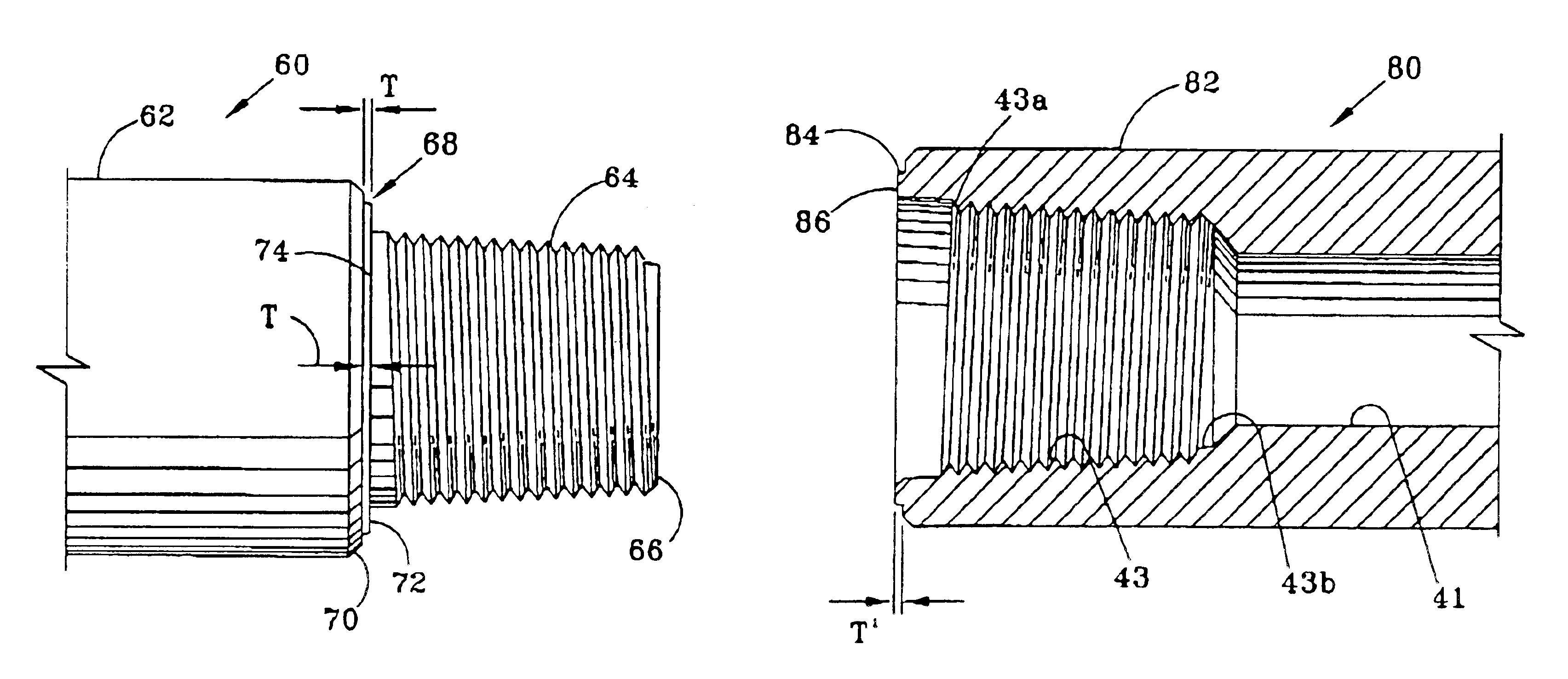
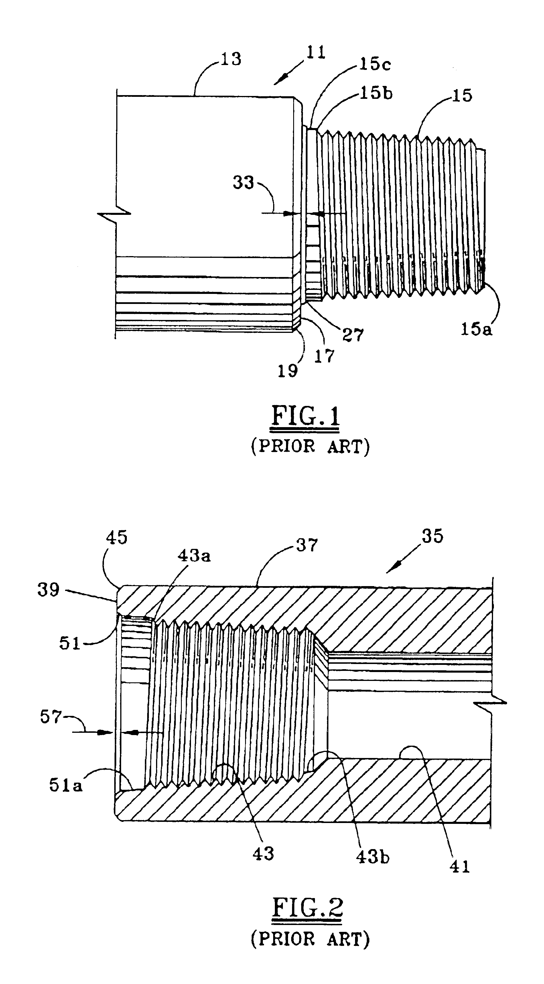
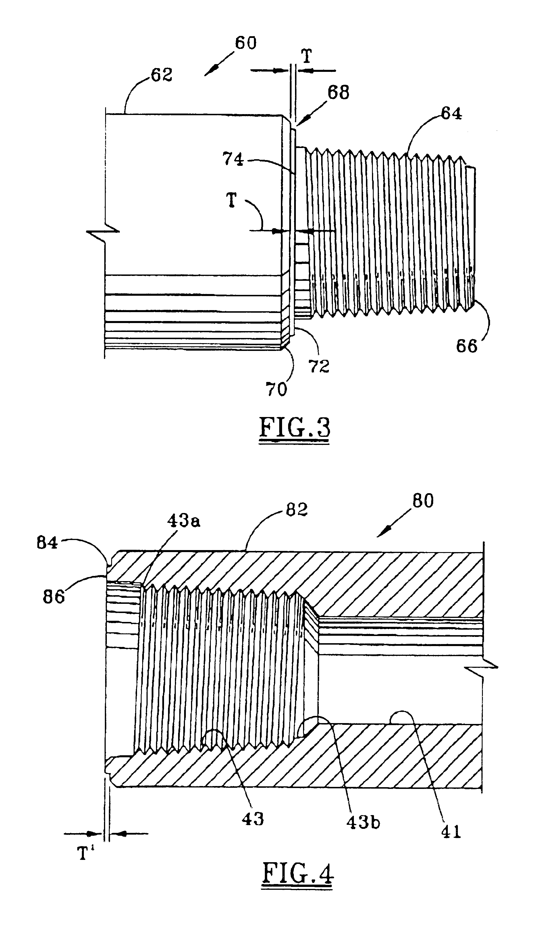
[0016]FIGS. 1 and 2 are provided to show a prior art tool joint bench mark, in order to gain a clearer understanding of the indicator of the present invention. A tool joint pin 11 for a drill pipe member has a cylindrical surface 13 containing an inner bore (not shown). External threads 15 are formed on the end of the cylindrical surface 13. The threads 15 have a first end 15a located at the extreme end of the tool joint pin 11. The threads 15 extend along the tool joint 11 for a selected distance, terminating at a second end 15b. The threads 15 are tapered, resulting in a smaller outer diameter at the first end 15a than at the second end 15b.
[0017]A make-up shoulder 17 is formed in the tool joint 11 a selected distance from the gage point of the threads 15 and inward from the end 15b. The make-up shoulder 17 is an annular surface located in a plane perpendicular to the axis of the tool joint pin 11. The make-up shoulder 17 faces outwardly and has a bevel 19 formed at its intersect...
PUM
 Abstract
Description
Claims
Application Information