Hydraulic braking system featuring selectable increased pump flow

Active Publication Date: 2005-05-24
CONTINENTAL AUTOMOTIVE SYST INC
View PDF3 Cites 16 Cited by
  • Summary
  • Abstract
  • Description
  • Claims
  • Application Information

AI Technical Summary

Benefits of technology

[0010]A further object of the invention is to provide a method for providing a rapid build-up of hydraulic pressure in a selected braking circuit of a dual-circuit braking system upon operation of the selected braking circuit's isolation valv

Problems solved by technology

Unfortunately, the addition of the pre-charge function to the master cylinder, or of an additional pre-chargi

Method used


Image

  • Hydraulic braking system featuring selectable increased pump flow
  • Hydraulic braking system featuring selectable increased pump flow
  • Hydraulic braking system featuring selectable increased pump flow

Examples


Example

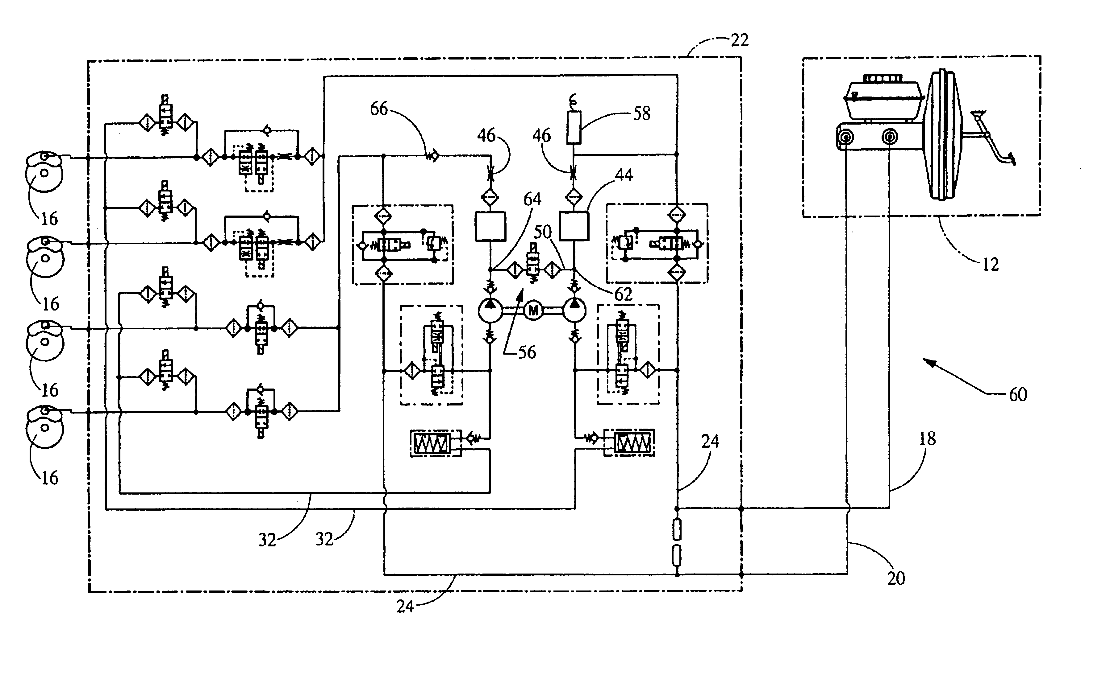
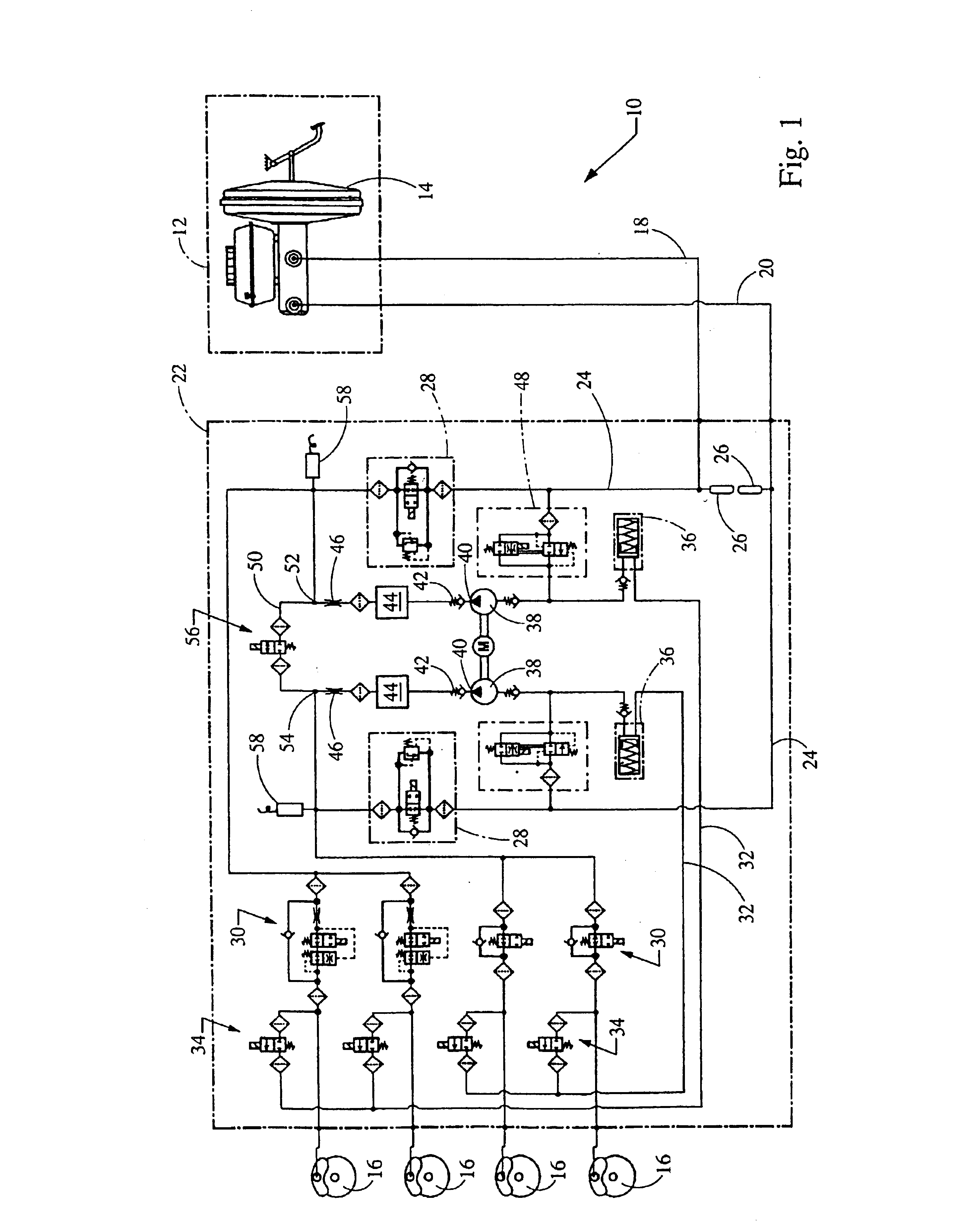
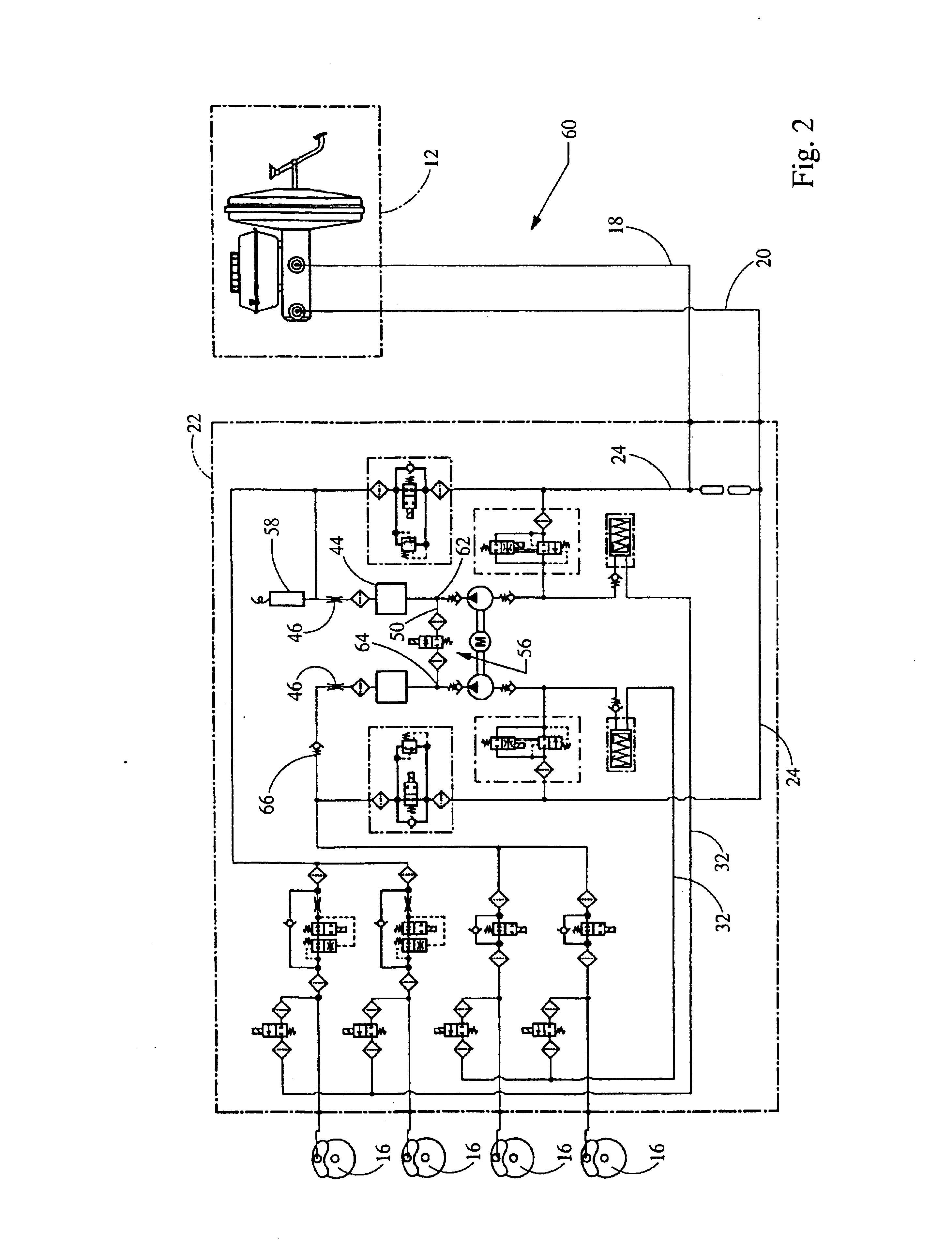
[0024]Referring to FIG. 1, a first exemplary hydraulic braking system 10 in accordance with the invention controls the flow of pressurized brake fluid from a brake actuation unit 12, such as a pedal-operated tandem master cylinder 14 that includes a vacuum brake booster by which to amplify the applied pedal force, to several wheel brakes 16 via a pair of braking circuits 18,20 conveniently housed within a hydraulic control unit 22. Specifically, each braking circuit 18,20 features a brake line 24 that receives pressurized fluid from the master cylinder 14 through a pulsation damper 26. Each brake line 24 includes a normally-open electrically-operated solation valve 28 whose operation is controlled by a system controller (not shown). Each brake line 24 is also selectively connected to each of a pair of wheel brakes 16 through a dedicated normally-open electrically-operated inlet valve 30, also operated by the system controller, to achieve anti-lock vehicle braking, vehicle traction c...


PUM


Abstract

An automotive braking system controls the flow of pressurized brake fluid from a tandem master cylinder to several wheel brakes via a pair of braking circuits. Each circuit features a pressure relief line having, in series, a normally-closed valve, low-pressure accumulator, pump, check valve, damping chamber, and throttling orifice. A bypass line includes a normally-closed bypass valve that is operated to interconnect the pressure relief lines of the first and second braking circuits downstream of the pump outlets to thereby reduce system response time when, for example, one or more wheel brakes are actuated to enhance vehicle traction or stability. Braking system redundancy is enhanced with a check valve incorporated in either or both circuits downstream of the bypass connection, or a second normally-closed bypass valve in the bypass line. Fluid pressure monitoring in either or both circuits is further useful in identifying bypass valve leakage.

Description

FIELD OF THE INVENTION[0001]The invention relates to dual-circuit hydraulic braking systems for a motor vehicle that are controlled to enhance vehicle traction or stability.BACKGROUND OF THE INVENTION[0002]Modern dual-circuit hydraulic braking systems for automotive applications typically include an operator-actuated brake actuation unit, such as a tandem master cylinder actuated by a booster-aided brake pedal, by which to supply a first pressurized fluid to each of a first pair of wheel brakes via a first or “primary” braking circuit, and a second pressurized fluid to each of a second pair of wheel brakes via a second or “secondary” braking circuit. The use of wholly redundant braking circuits for operating discrete pairs of wheel brakes ensures continued vehicle braking capability, notwithstanding a degradation of performance of the one of the braking circuits.[0003]In order to achieve an “anti-lock” braking system, each braking circuit often features a normally-open electrically-...

Claims


Application Information

Patent Timeline
IPC IPC(8): B60T8/40B60T8/48B60T8/36B60T8/175
CPCB60T8/363B60T8/4872B60T8/405
Inventor NAKAYASU, YUJITRUAX, JOHN T.
Owner CONTINENTAL AUTOMOTIVE SYST INC
Why Eureka
Try Eureka