Automated latching device with active damping

a technology of automatic latching and damping, which is applied in the direction of couplings, manufacturing tools, cosmonautic vehicles, etc., can solve the problems of additional problems such as the buildup of vibrations in the latch structure, and achieve the effects of correcting and repeating the process, and discharging any vibrational energy

Inactive Publication Date: 2005-05-24
LOCKHEED MARTIN CORP
View PDF10 Cites 25 Cited by
  • Summary
  • Abstract
  • Description
  • Claims
  • Application Information

AI Technical Summary

Benefits of technology

[0004]Embodiments of the present invention are directed to a compact and lightweight, automated latching device which includes a passive catch configured to be engaged with a motor-powered latch to form a mechanical connection between two structure in a precise and repeatable manner. An integrated active damping mechanism is used to dissipate any vibrational energy that may be present in the latched structure. The apparatus may be used to precisely orient and attach a deployable element, usually of a space vehicle, to the main body of the vehicle. In operation, the passive catch is brought into close proximity to the latch during the terminal phase of the deployment sequence. When the catch is sufficiently close to the latch, the latch mechanism is energized and the catch is automatically pulled into and captured by the latch and held in the correct mating position by a spring with a predetermined preload. In an exemplary embodiment, the mating surfaces of the latch and the catch are a spherical catch surface and a conical latch interface, so that the mated geometry is both correctly constrained and very precise.
[0005]As the catch becomes mated to the latch, an actuator (e.g., a coaxial linear voice coil motor) which is mounted to the outer body or damper housing of the latch is engaged with the catch. Because the catch contains an integral flexure that allows for a calibrated compliance in the axial direction between the deployed structure and the main body of the vehicle, the linear motor can provide an actuation force at the latched joint between the two bodies. This force, if controlled correctly, will act to dissipate any vibrational energy in the deployed structure. This technique is effective because the one or more latch apparatus that attach the deployed structure to the main body are typically the only or primary mechanical paths by which vibrations can be transmitted between the two bodies. Therefore, the energy absorbing feature within the latches is a direct way of reducing or eliminating mechanical energy originating in the main body.

Problems solved by technology

It is a challenge to provide precise and repeatable mechanical connection between two separate portions of a spacecraft or a spacecraft and another structure such that they behave as a unitary structure.
In some cases, the buildup of vibrations in the latched structure presents additional problems.

Method used


Image

  • Automated latching device with active damping
  • Automated latching device with active damping
  • Automated latching device with active damping

Examples


Embodiment Construction

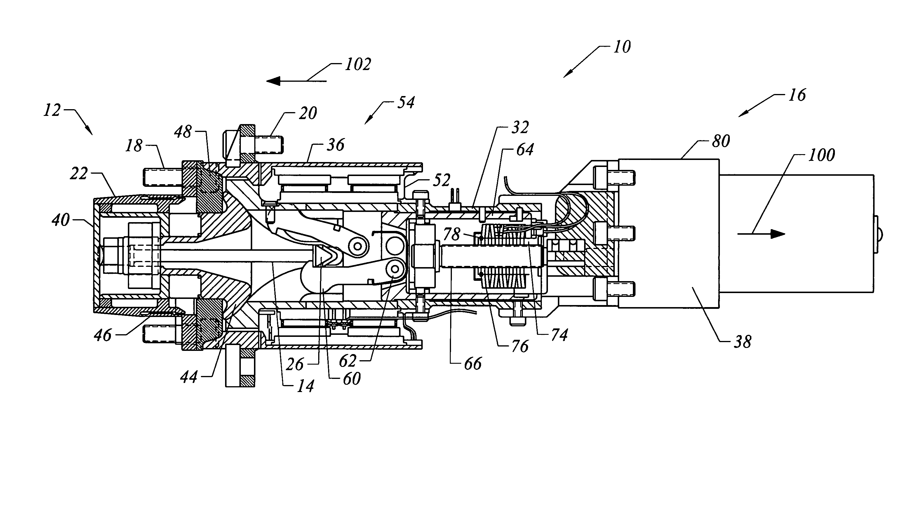
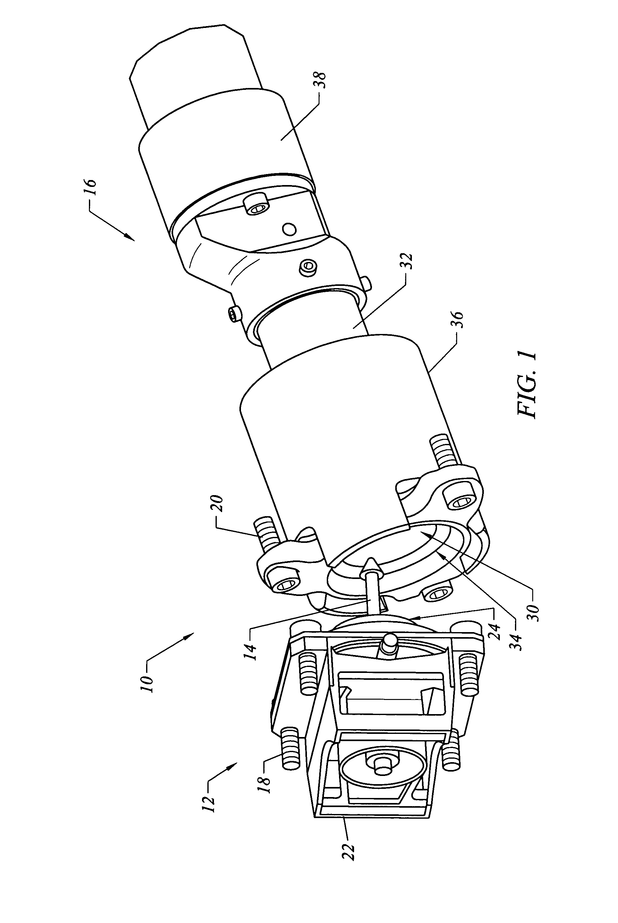
[0019]FIG. 1 shows a latching apparatus 10 which includes a catch 12 having a probe 14 that is to be gripped by a latch 16. The catch 12 and the latch 16 are coupled to separate structures that are to be connected together to act as a unitary structure. For example, fasteners 18 are used to attach the catch 12 to a first structure which may be a portion of a spacecraft, a structure to be deployed, or the like, and fasteners 20 are used to attach the latch 16 to a second structure which may be another portion of the spacecraft, a spacecraft, or the like. Typically, a plurality of latching apparatus 10 are used to connect the two structures. For example, three latching apparatus 10 are used provide a stable mounting mechanism.

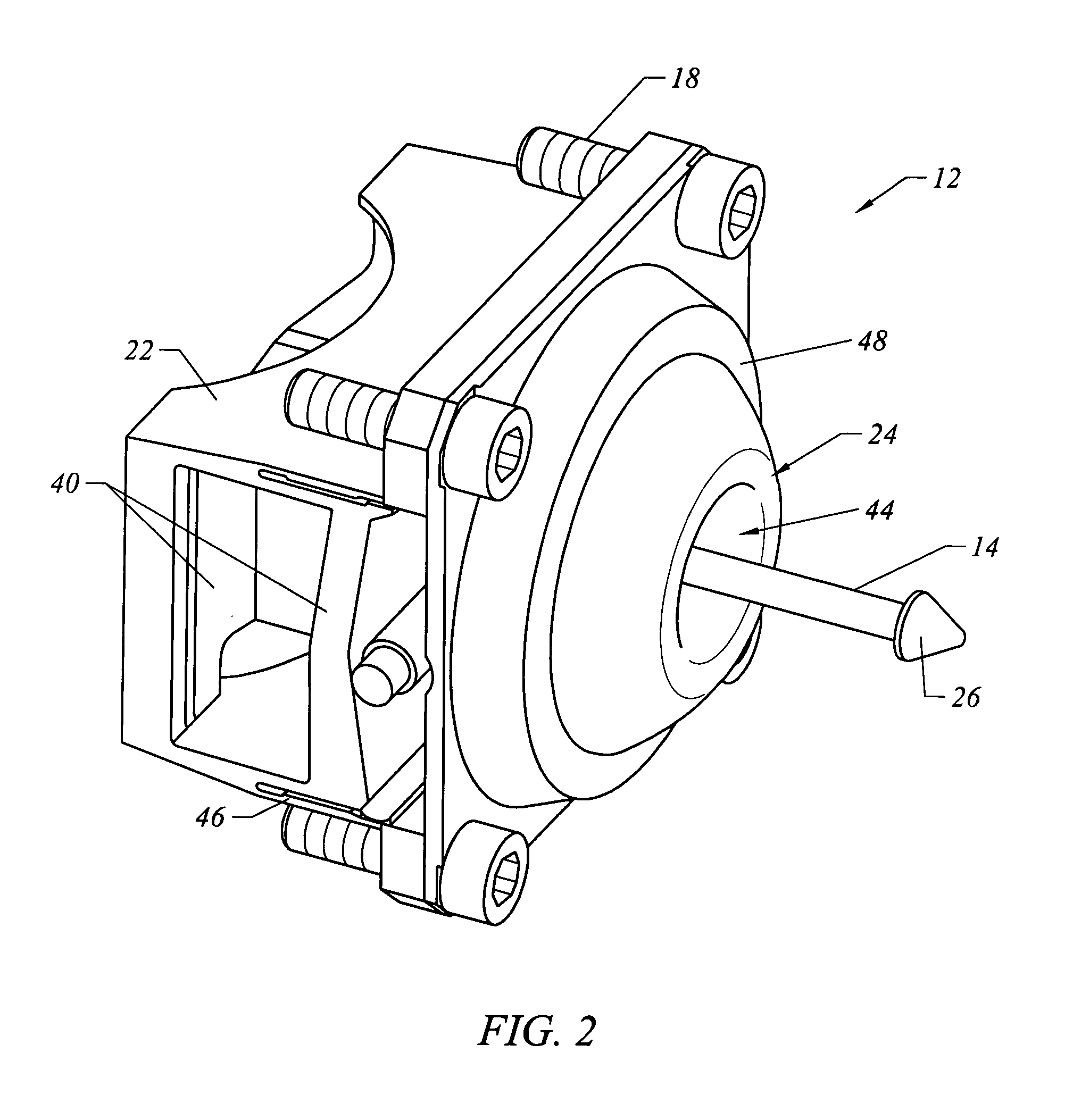
[0020]As seen in FIGS. 1 and 2, the catch 12 includes a catch body 22 and a catch interface surface or catch surface 24 which is generally spherical in shape in the embodiment shown. The probe 14 extends through an axis of the catch body 22 and catch surface 24 t...


PUM


Abstract

Embodiments of the present invention are directed to a compact and lightweight, automated latching device which includes a passive catch configured to be engaged with a motor-powered latch to form a mechanical connection between two structure in a precise and repeatable manner. An active damping mechanism is used to dissipate any vibrational energy that may be present in the latched structure. The apparatus may be used to precisely orient and attach a deployable element, usually of a space vehicle, to the main body of the vehicle. In one embodiment, a latching apparatus comprises a catch having a catch body and a probe connected to the catch body. A latch has a main housing and a grip mechanism movable relative to the main housing. The grip mechanism is configured to grip the probe and to be actuatable to pull the probe toward the latch. A damping member is coupled with the main housing of the latch, and is movable relative to the main housing of the latch toward the catch. The damping member is actuatable to exert a damping force against the catch body of the catch.

Description

CROSS-REFERENCES TO RELATED APPLICATIONS[0001]This application is based on and claims the benefit of U.S. Provisional Patent Application No. 60 / 402,907, filed Aug. 14, 2002, the entire disclosure of which is incorporated herein by reference.BACKGROUND OF THE INVENTION[0002]The present invention relates generally to latching devices and, more particularly, to a latching device having an active damping mechanism to dissipate vibrational energy.[0003]Latching devices are used in space applications to deploy large structures such as antenna reflectors, solar arrays, mirrors, and the like. It is a challenge to provide precise and repeatable mechanical connection between two separate portions of a spacecraft or a spacecraft and another structure such that they behave as a unitary structure. In some cases, the buildup of vibrations in the latched structure presents additional problems.BRIEF SUMMARY OF THE INVENTION[0004]Embodiments of the present invention are directed to a compact and lig...

Claims


Application Information

Patent Timeline
Patent Type & Authority Patents(United States)
IPC IPC(8): B64G1/64B64G1/22
CPCB64G1/645B64G1/222Y10T403/60
Inventor CHAMPAGNE, PATRICK JOSEPHLORELL, KENNETH ROY
Owner LOCKHEED MARTIN CORP
Why Eureka
Try Eureka